

Access method, access system and mobile intelligent access point
A technology of mobile intelligence and access method, which is applied in the field of communication to achieve network authentication, reduce dependencies, and secure the network
- Summary
- Abstract
- Description
- Claims
- Application Information
AI Technical Summary
Problems solved by technology
Method used
Image

Examples
Embodiment 1
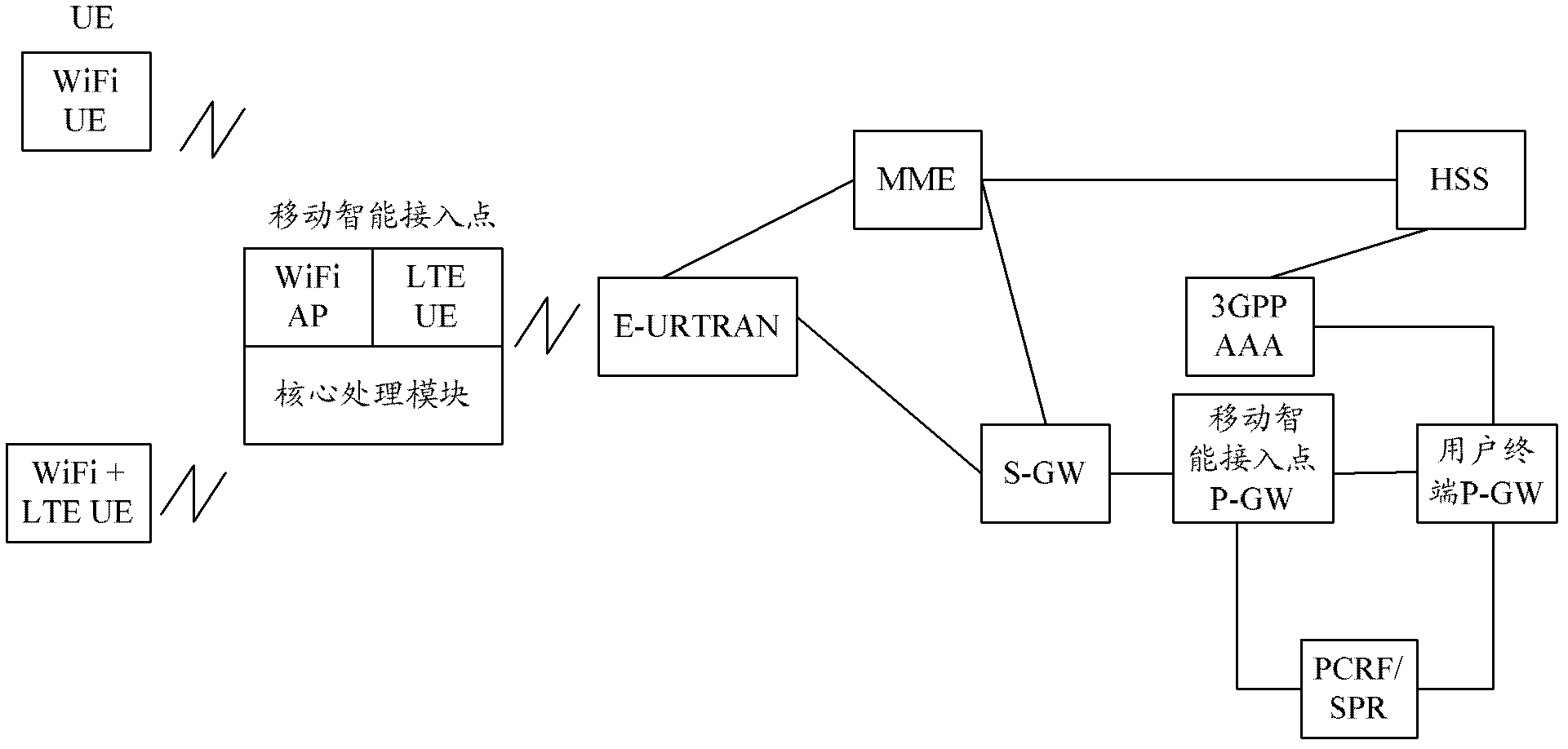
[0075] image 3 is a schematic structural diagram of an access system provided by Embodiment 1 of the present invention, as shown in image 3 As shown, compared with the existing EPS architecture, the system adds a mobile intelligent access point, which is mainly composed of the following three parts: LTE UE module, WIFI AP module and core processing module; among them,
[0076] The LTE UE module is used for the mobile intelligent access point to access the LTE core network through the E-UTRAN network, providing high broadband resources for the mobile intelligent access point;
[0077] The WIFI AP module is a module for WIFI terminal access processing. Terminals with WIFI functions can access through mobile intelligent access points, and perform related HTTP services after passing network authentication;
[0078] The core processing module executes the mutual conversion processing between WIFI message / data and LTE message / data.
[0079] The mobile smart access point can also...
Embodiment 2
[0083] Figure 4 with Figure 5 They are schematic diagrams of a control plane protocol stack and a user plane protocol stack in Embodiment 2 of the present invention, respectively.
[0084] Such as Figure 4 The control plane protocol stack shown, where L2 / L1 (Layer 1 / Layer 2, Layer 1 / Layer 2) are the data link layer and the physical layer respectively, and the mobile intelligent access point and E-UTRAN, S-GW and P - The GW establishes the GTP-U user plane protocol stack, and then the mobile intelligent access point establishes an MIPv4 or PMIPv6 signaling tunnel with the P-GW of the user terminal to transmit messages convenient for signaling.
[0085] Such as Figure 5 As shown in the user plane protocol stack, the same mobile intelligent access point establishes a GTP-U user plane protocol stack with E-UTRAN, S-GW and P-GW, and the mobile intelligent access point and the user terminal P-GW Establish an MIPv4 or PMIPv6 user plane tunnel, thereby opening up the IP connec...
Embodiment 3
[0087] Image 6 It is a schematic flow diagram of a user equipment accessing a network through a mobile intelligent access point in Embodiment 3 of the present invention, as shown in Image 6 As shown, the process includes:
[0088] In steps 601-602, when the mobile intelligent access point is powered on, it initiates an attach process and registers in the core network. The non-access stratum message is encapsulated by the base station (E-UTRAN) in the initialization user message of the S1 interface and sent to the MME.
[0089] Step 603, if there is no context information of the user in the network, or the attach request message has no integrity protection, or the integrity protection fails, then the MME of the core network performs an authentication process for the user.
[0090] Steps 604-605, if there is no subscription data of the user in the MME, then send a location update request message to the Home Subscriber Server (3GPP AAA / HSS), which includes information such as m...
PUM
 Abstract
Description
Claims
Application Information