Unit and method for conveying workpieces along a processing run

一种输送方向、设备的技术,应用在输送机物件、输送机、运输和包装等方向,能够解决增高事故可能性等问题,达到节省空间位置的效果

Inactive Publication Date: 2013-02-13
DUERR SYST GMBH
View PDF7 Cites 3 Cited by
  • Summary
  • Abstract
  • Description
  • Claims
  • Application Information

AI Technical Summary

Problems solved by technology

Continuous conveying devices are thus reliable because they are operated with fewer drive motors, while the unique clocked support of clocked machines has an increased risk of accidents due to the multiple individually controllable motors

Method used


Image

  • Unit and method for conveying workpieces along a processing run
  • Unit and method for conveying workpieces along a processing run
  • Unit and method for conveying workpieces along a processing run

Examples


Embodiment Construction

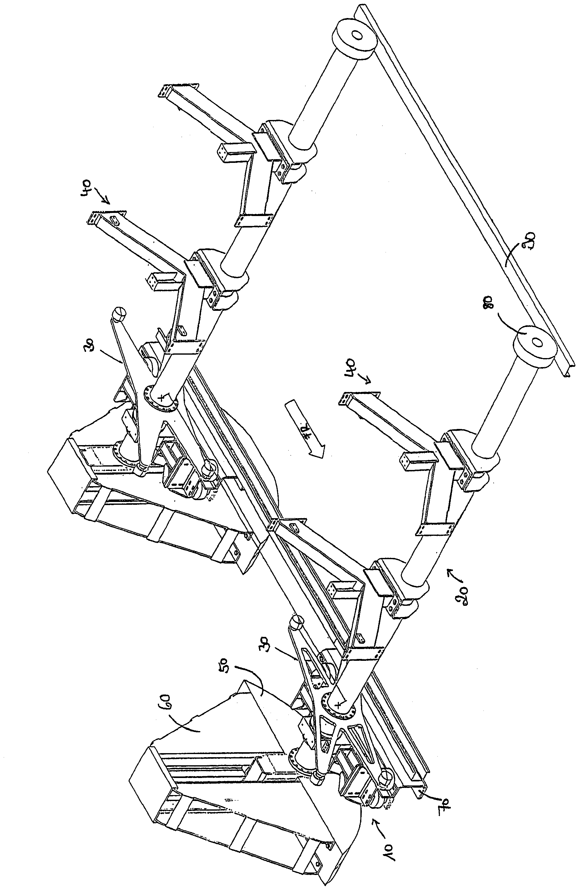
[0041] exist figure 1 A schematic general view of the apparatus of the present invention is depicted in .

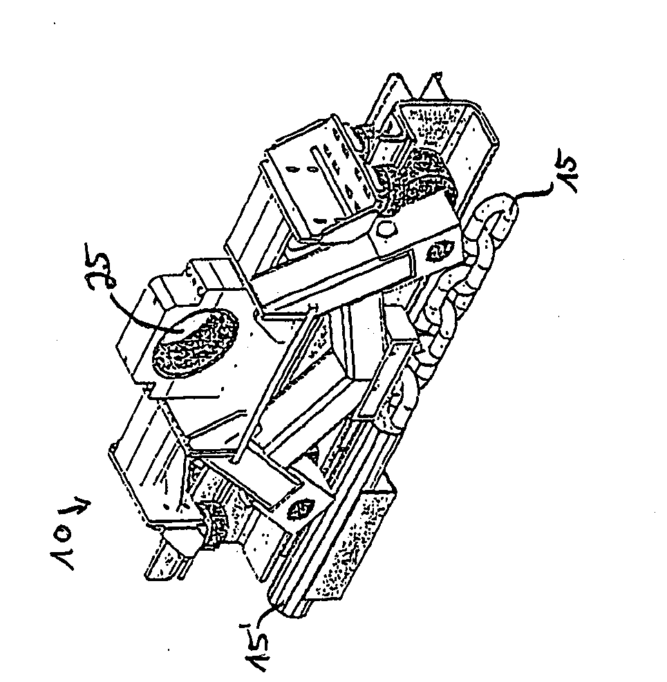
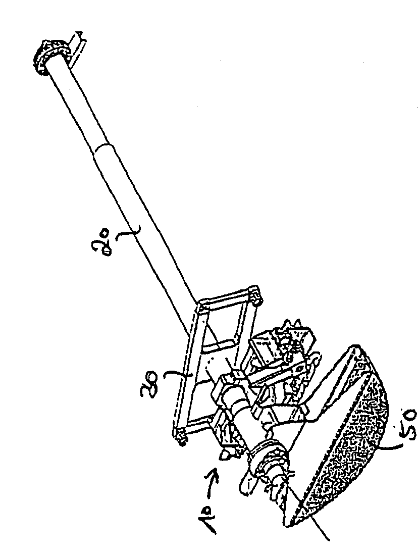
[0042] With this device, workpieces can be transported through a processing station. In particular, such a device can be used to guide body components through a dip in order to paint these components. For this purpose, the device has several workpiece holders, which are figure 1 Two of them are described in , and the tool holders are each formed by a transport carriage 10 and a pivot 20 as basic components.

[0043] The shafts 20 themselves each have a bracket 40 on which the body components to be painted can be mounted directly or via a so-called slide. The shaft 20 is rotatably mounted on the transport carriage 10 and moves together with the transport carriage 10 along a guide rail 70 in a transport direction designated "FR". For this purpose, the transport carriage 10 is driven, for example, by means of a conveyor chain, a rope or a belt. Next to the guide rail 7...


PUM


Abstract

The invention relates to a unit and method for conveying workpieces along a processing run, comprising at least one transport car (10), moving along the processing run in a conveying direction (FR) and a rotating shaft (20), mounted on the transport car (10), close to a first of the ends thereof, to rotate about the axis thereof at right angles to the conveying direction (FR) and on which a mounting (40) for the workpiece to be processed is provided. The rotating shaft (20) is only mounted close to the first end thereof on the transport car (10) and may thus be driven in the conveying direction (FR), whereupon the second free end thereof is passively transported along in the conveying direction (FR). It is thus possible to pivot the rotating shaft (20) in a plane running at right angles to the conveying direction, in particular, to permit a space saving return.

Description

[0001] This application is a patent with an international application date of April 18, 2005, an invention titled "Equipment and Method for Conveying Workpieces Along Processing Lines", and a national application number of 200580016018.X (international application number is PCT / EP2005 / 004106) Divisional application of the application. technical field [0002] The invention relates to a device for conveying workpieces on a processing line. [0003] Along such a processing line there is at least one, but mostly a plurality of processing stations arranged one behind the other, into which the workpieces for surface treatment are fed. [0004] A treatment station can be, for example, an immersion tank with treatment liquid, but the term treatment station can also be understood to mean any other type of chamber or tank in which a workpiece is treated. This treatment can also include, for example, a cleaning process. Further examples for treatments are a dip phosphating, pretreatme...

Claims


Application Information

Patent Timeline
Patent Type & Authority Applications(China)
IPC IPC(8): B65G49/04
CPCB65G49/0463B65G49/0459B65G2812/02128B65G2812/02326
Inventor H.穆勒J.文克勒K.克罗姆布霍尔茨
Owner DUERR SYST GMBH
Why Eureka
Try Eureka