Unit and method for conveying workpieces along a processing run

A technology of conveying direction and equipment, applied in the direction of conveyor objects, conveyors, transportation and packaging, etc., can solve the problems of increasing the possibility of accidents, and achieve the effect of saving space and location

Inactive Publication Date: 2007-08-22
迪尔系统有限责任公司
View PDF3 Cites 11 Cited by
  • Summary
  • Abstract
  • Description
  • Claims
  • Application Information

AI Technical Summary

Problems solved by technology

Continuous conveying devices are thus reliable because they are operated with fewer drive motors, while the unique clocked support of clocked machines has an increased risk of accidents due to the multiple individually controllable motors

Method used


Image

  • Unit and method for conveying workpieces along a processing run
  • Unit and method for conveying workpieces along a processing run
  • Unit and method for conveying workpieces along a processing run

Examples


Embodiment Construction

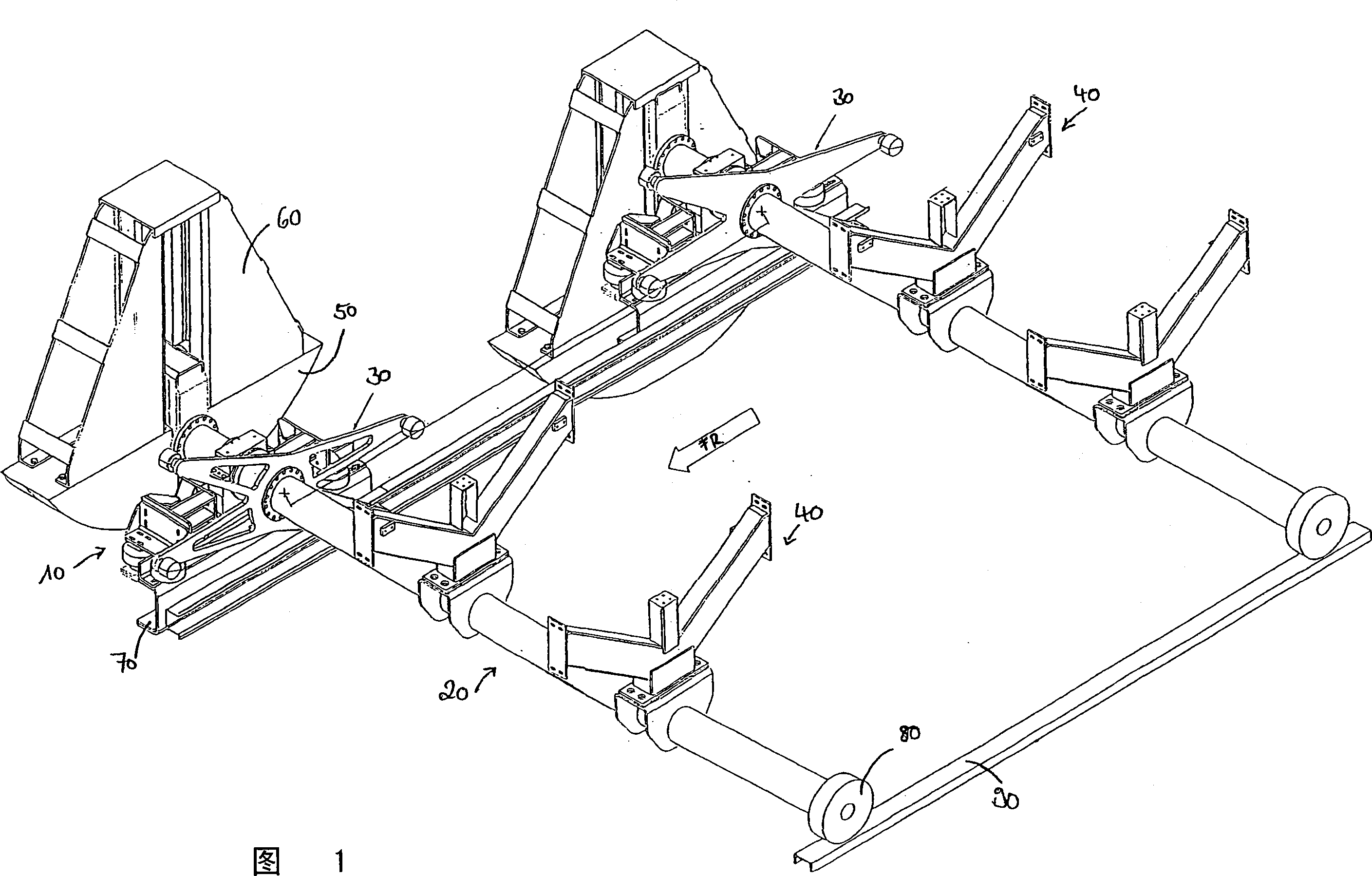
[0040] A schematic general view of the device according to the invention is depicted in FIG. 1 .

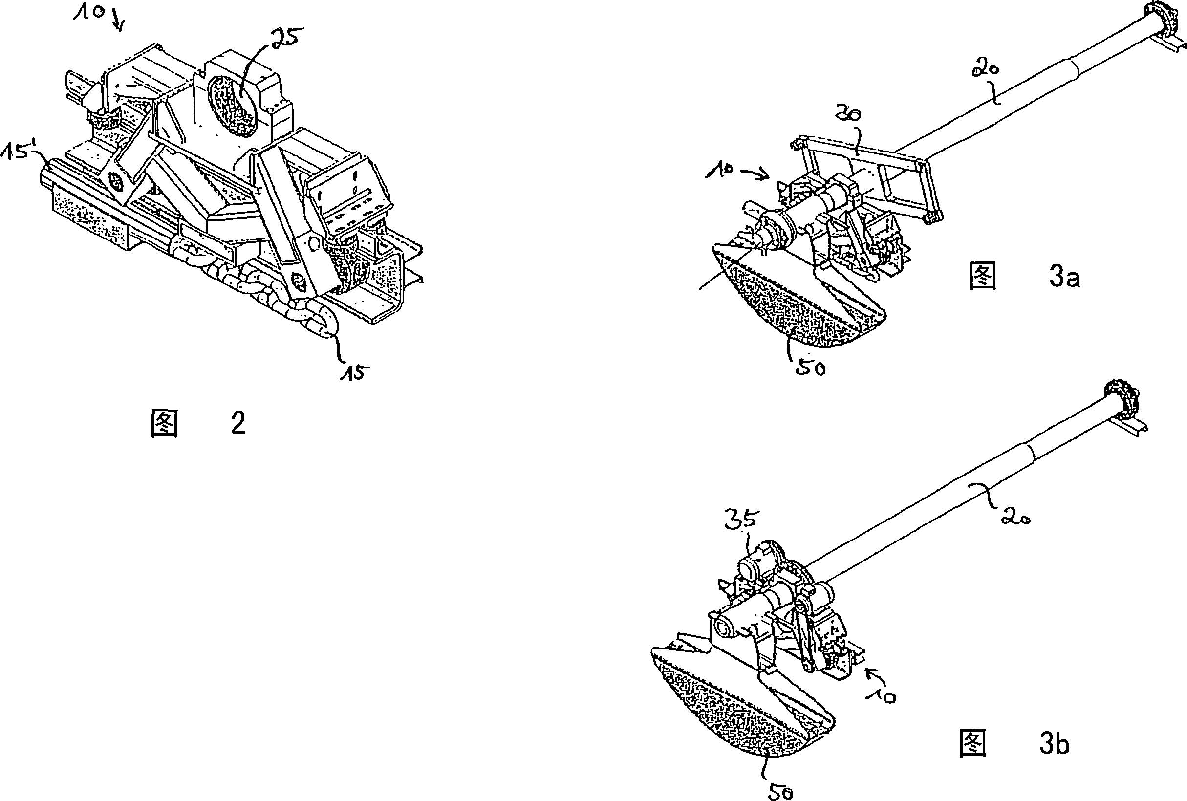
[0041] With this device, workpieces can be conveyed through a processing station. In particular, such a device can be used for passing body components through a dipping process in order to paint these components. For this purpose, the device has a plurality of tool holders, two of which are depicted in FIG. 1 and which are each formed as basic components by a transport carriage 10 and a rotary shaft 20 .

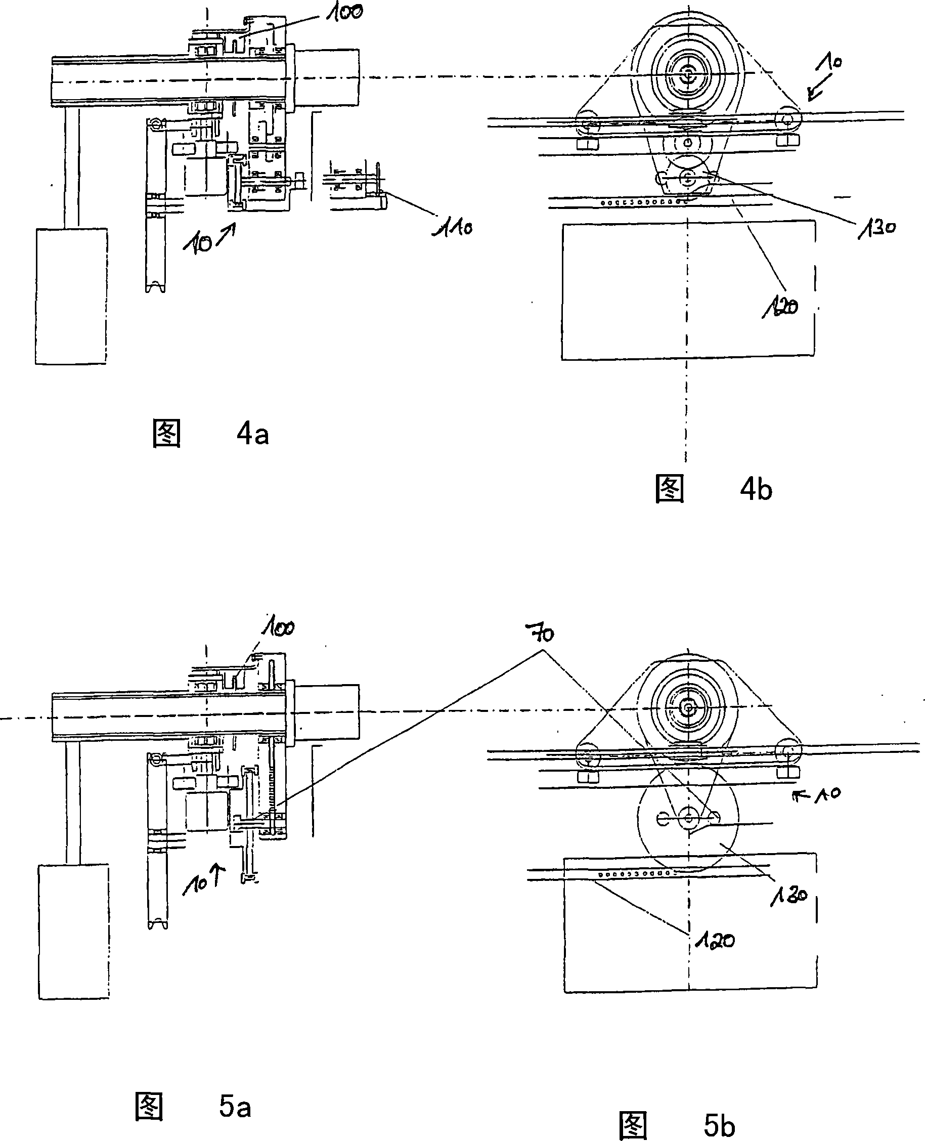
[0042]The spindles 20 themselves each have a carrier 40 , on which body components to be painted can be mounted directly or via so-called slide plates. The rotary shaft 20 is rotatably mounted on the transport vehicle 10 and moves together with the transport vehicle 10 along a guide rail 70 in a transport direction designated by "FR". For this purpose, the conveyor trolley 10 is driven, for example, by means of a conveyor chain, a cable or a belt. A dipping tank (not shown) ...


PUM


Abstract

The invention relates to a unit and method for conveying workpieces along a processing run, comprising at least one transport car (10), moving along the processing run in a conveying direction (FR) and a rotating shaft (20), mounted on the transport car (10), close to a first of the ends thereof, to rotate about the axis thereof at right angles to the conveying direction (FR) and on which a mounting (40) for the workpiece to be processed is provided. The rotating shaft (20) is only mounted close to the first end thereof on the transport car (10) and may thus be driven in the conveying direction (FR), whereupon the second free end thereof is passively transported along in the conveying direction (FR). It is thus possible to pivot the rotating shaft (20) in a plane running at right angles to the conveying direction, in particular, to permit a space saving return.

Description

technical field [0001] The invention relates to a device for conveying workpieces on a processing line. [0002] Along such a processing line there is at least one, but mostly a plurality of processing stations arranged one behind the other, into which the workpieces for surface treatment are fed. [0003] A treatment station can be, for example, an immersion tank with treatment liquid, but the term treatment station can also be understood to mean any other type of chamber or tank in which a workpiece is treated. This treatment can also include, for example, a cleaning process. Further examples for treatments are a dip phosphating, pretreatment for dip painting, powder coating, wet paint coating and similar processes. Background technique [0004] The hitherto known devices for surface treatment of workpieces, such as motor vehicle bodies, in immersion tanks or treatment chambers are subdivided into continuously conveyed devices and discontinuously conveyed devices. [00...

Claims


Application Information

Patent Timeline
Patent Type & Authority Applications(China)
IPC IPC(8): B65G49/04
CPCB65G49/0463B65G49/0459B65G2812/02128B65G2812/02326
Inventor H·穆勒J·文克勒K·克罗姆布霍尔茨
Owner 迪尔系统有限责任公司
Why Eureka
Try Eureka