Sealing structure of explosion proof purification light fitting

A technology for sealing structures and lamps, which is applied in the direction of air-proof/waterproof devices, lighting devices, and parts of lighting devices, etc. It can solve the problems of poor purification effect of lamps, influence on dust-proof conditions, and influence on purification effects, etc., and achieve material reduction consumption, improve heat dissipation, and save material cost

Inactive Publication Date: 2013-02-13
陆阳 +1
View PDF4 Cites 6 Cited by
  • Summary
  • Abstract
  • Description
  • Claims
  • Application Information

AI Technical Summary

Problems solved by technology

This kind of lamp cover 2 is in surface contact with the sealing ring 11. Once some parts of the contact surface warp, there will be relatively large gaps, which are easy to accumulate dust and affect the purification effect.
[0007] There is a hidden danger in the sealing structure of the above-mentioned explosion-proof purification lamps. Since the sealing screws directly penetrate into the explosion-proof chamber, once individual sealing screws fall off, the explosion-proof chamber is directly exposed to the production environment. Once the electric spark is conducted, it will cause a great safety hazard.
In addition, the purification effect of this kind of lamp is not good. Because the sealing ring is usually made of rubber, the rubber is very easy to become sticky under the high temperature emitted by the lamp, attracting dust to accumulate, which seriously affects the dustproof situation of the chemical, pharmaceutical, food and other industries; It is also easy to age under the high temperature emitted, and the seal is easy to fail

Method used


Image

  • Sealing structure of explosion proof purification light fitting
  • Sealing structure of explosion proof purification light fitting
  • Sealing structure of explosion proof purification light fitting

Examples


no. 1 example

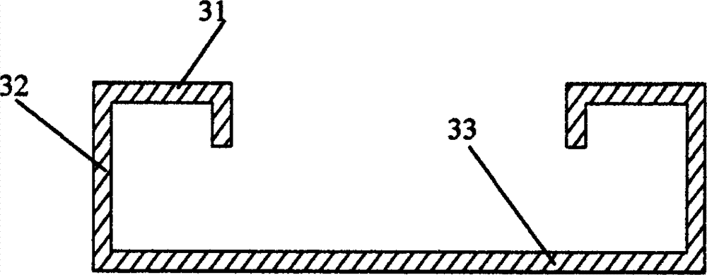
[0045] Such as Figure 5 , the bottom wall 33 is a hollow frame on the plane, the top wall 31 is a concave platform 311 formed by the middle part being recessed toward the direction of the bottom wall 33, and the lamp pin 4 is arranged on the concave platform 311 through the lamp holder. There is a gap between the concave platform 311 and the side wall 32 to form a channel.

[0046] Such as Figure 6 , The lower part of the sealing screw 13 is located in the gap between the concave platform 311 and the side wall 32, so the sealing screw is isolated from the explosion-proof chamber to enhance safety.

[0047]In addition, the trench can significantly improve the heat dissipation of the entire lamp. For integral molding, convenient installation and aesthetics, the bottom of the recessed platform 311 is usually flat and flush with the bottom wall 33 .

[0048] The fixation of the lampshade 1 in this embodiment still uses the existing mode, the lamp cover 2 and the pressure plat...

no. 2 example

[0051] Such as Figure 7 , an explosion-proof purification lamp sealing structure, including detachably connected lampshade 1, lamp cover 2, base 3 in sequence; base 3 includes a top wall 31 connected to the lamp cover 2, a bottom wall 33 connected to the ceiling and a connecting top wall 31 With the four side walls 32 of the bottom wall 33 , the bottom wall 33 is a hollow frame on the plane, and the middle part of the top wall 31 is recessed toward the bottom wall 33 to form a concave platform 311 , and there is a gap between the concave platform 311 and the side wall 32 .

[0052] The lower part of the lampshade 1 is connected with the lamp cover 2 through fastening screws 12 , and a sealing ring 11 is arranged between the lower part of the lampshade 1 and the top end of the top wall 31 . The width of the sealing ring 11 can cover the bottom surface of the lower part of the lampshade 1 .

[0053] Figure 7 The end of the lower part of the lampshade 1 shown is bent upwards,...

no. 3 example

[0058] Such as Figure 8 The other parts of this embodiment are the same as those of the second embodiment, the difference is that there are two convex strips 101 at the bottom of the lower part of the lampshade 1, the fastening screw 12 is arranged between the two convex strips 101, and the upper part of the sealing ring 11 is clamped Between the two convex strips 101.

[0059] The width of the lower section of the sealing ring 11 is greater than that of the upper section, shoulders are formed on both sides of the middle section of the section, and the two convex lines 101 on the lower part of the lampshade 1 are respectively supported on the shoulders on both sides. The bottom of the section of the sealing ring 11 is arc-shaped.

[0060] In this embodiment, the cooperation between the convex strip 101 and the seal ring 11 can compress the seal ring 11 without displacement. Especially the bottom 11 of the sealing ring is arc-shaped, as long as the sealing screws are tighten...


PUM


Abstract

The invention relates to a light fitting sealing structure and especially relates to a sealing structure of explosion proof purification light fitting. The sealing structure of explosion proof purification light fitting comprises a lampshade, a lamp cover and a pedestal, which are detachably connected together in sequence; the pedestal comprises a top wall connected with the lamp cover, a bottom wall connected with the ceiling and four side walls connected with the top wall with the bottom wall, the lamp cover is connected with a pressing plate through a fastening screw, and the lower part of the lampshade is firmly clamped between the lamp cover and the pressing plate; a sealing ring is arranged between the pressing plate and the top wall, a sealing screw sequentially passes through the lamp cover, the sealing ring and the top wall, the bottom wall is a hollow frame on the plane, the middle part of the top wall depresses towards the direction of the bottom wall to form a depression, and a segment of gap exists between the depression and the side walls; and the lower part of the sealing screw is located in the gap between the depression and the side walls. The sealing screw of the sealing structure of explosion proof purification light fitting disclosed by the invention is isolated at the outside of the explosion proof cavity to improve the safety performance, improve the radiating conditions and improve the purification effect.

Description

technical field [0001] The invention relates to a lamp sealing structure, in particular to an explosion-proof purification lamp sealing structure. Background technique [0002] Explosion-proof purification lamps installed with fluorescent tubes are widely used in chemical industry, medicine, biotechnology, electronics, food, military industry, petroleum and other fields that require explosion-proof and dust-proof purification lighting. The basic structure of explosion-proof purification lamps is as follows: figure 1 , including a light-transmitting lampshade 1 , a lamp cover 2 and a base 3 . [0003] There are lamp holders (omitted in the figure) on both sides of the base 3, and the lamp pins 4 are arranged on the lamp holders. After removing lampshade 1 and lamp cover 2, if figure 2 As shown, a plurality of fluorescent lamp tubes 5 are inserted on the lamp pins 4 , and a reflector (omitted in the figure) is arranged between the base 3 and the lamp tubes 5 . Electrical ...

Claims


Application Information

Patent Timeline
Patent Type & Authority Applications(China)
IPC IPC(8): F21V31/00
Inventor 陆阳陆国富
Owner 陆阳
Why Eureka
Try Eureka