Ceramic capacitive pressure sensor

A pressure sensor and ceramic capacitor technology, applied in the field of ceramic capacitive pressure sensors, can solve the problem of difficulty in precise control of the thickness of annular spacer piers

Active Publication Date: 2013-02-13
SHENZHEN AMPRON TECH CORP
View PDF8 Cites 26 Cited by
  • Summary
  • Abstract
  • Description
  • Claims
  • Application Information

AI Technical Summary

Problems solved by technology

[0006] The method of D-240500 mentioned above uses small balls to solve the problem of the accuracy of the spacers, but it cannot avoid the problem of the flow of welded ...

Method used


Image

  • Ceramic capacitive pressure sensor
  • Ceramic capacitive pressure sensor
  • Ceramic capacitive pressure sensor

Examples


Embodiment Construction

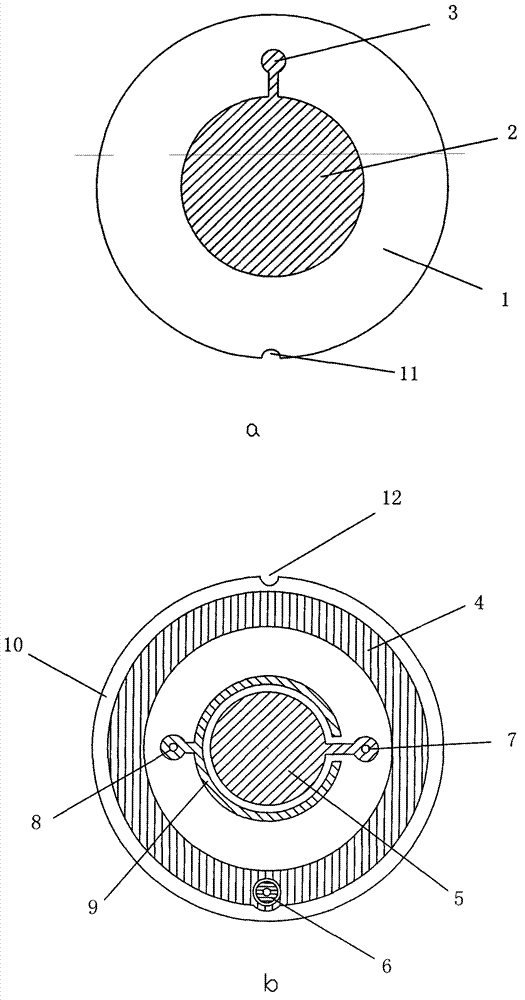
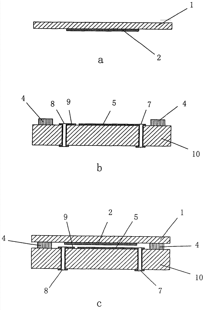
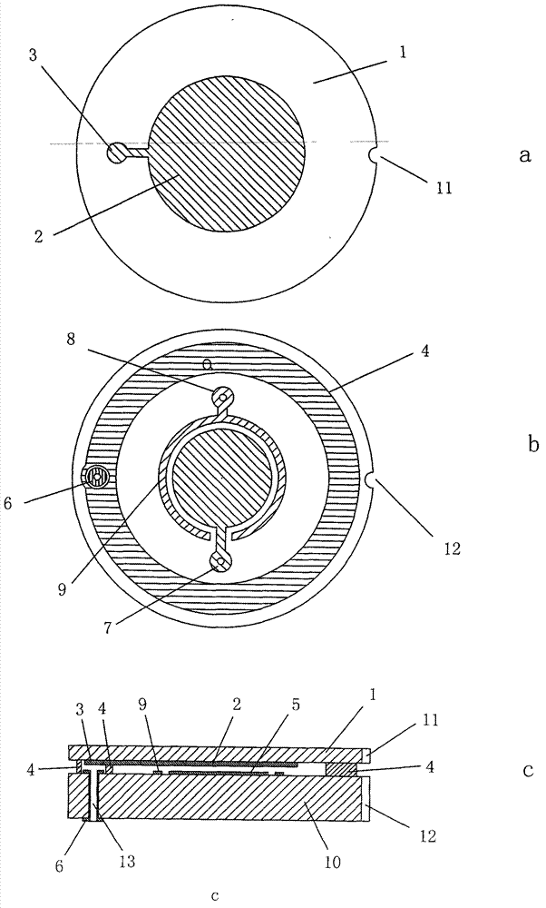
[0021] as attached figure 1 . Shown: figure 1 In a, (1) is the ceramic cover plate, which is the thinner of the two ceramic substrates, with a thickness of only 0.2-1.2mm. The pressure sensor is subjected to external pressure, mainly because the ceramic cover plate will produce elastic bending in the thickness direction. A layer of metal electrodes with a thickness of 0.2-0.6 μm is made on the surface of the circular ceramic cover plate by screen printing or vacuum sputtering, that is, the cover plate electrode (2), and the lead pad (3) is connected next to the electrode (2). The edge of the ceramic cover plate (1) is provided with a cover plate positioning notch (11).

[0022] figure 1 In b, (10) is a ceramic substrate, which is the thicker one of the two ceramic substrates, with a thickness of 3-6mm. The same method is used on the circular ceramic substrate surface to make a layer of 0.2-0.6 μm thick metal electrode, i.e. the substrate electrode (5), and the ring electrod...


PUM

PropertyMeasurementUnit
Thicknessaaaaaaaaaa

Abstract

The invention provides a ceramic capacitive pressure sensor and relates to an electrostatic capacitive pressure sensor and a manufacturing process of the ceramic capacitive pressure sensor. At present, according to the electrostatic capacitive pressure sensor, plate electrodes are respectively arranged on the surfaces of two ceramic substrates, so that a small gap is formed between the two electrodes, the two electrodes are parallelly opposite to each other, the two parallel ceramic substrates are fixed into a whole to form a plate condenser, and the pressure is detected by testing the capacitance change under pressure. The capacitance is determined by the distance between polar plates, so that the pressure detection accuracy is influenced; and therefore, the distance between the electrodes must be accurately controlled. An annular low temperature co-fired ceramic (LTCC) green sheet is arranged between two plates, the LTCC green sheet and the two plates are stacked together, clamped by a clamp and sintered into a whole at a certain temperature, and the accurate distance and pressure detection precision between the polar plates are guaranteed.

Description

technical field [0001] The invention relates to an electrostatic capacitive pressure sensor and a manufacturing process thereof. Background technique [0002] At present, the electrostatic capacitive pressure sensor is provided with flat electrodes on the surfaces of two ceramic substrates, so that the two electrodes are separated by a small gap in parallel, and the two parallel ceramic substrates are fixed together to form a flat capacitor. When the above-mentioned substrate is subjected to external pressure, elastic bending occurs in the thickness direction of the plate, resulting in a change in electrostatic capacitance value. By detecting the change in capacitance value, the external pressure on the above-mentioned substrate can be obtained. [0003] Because the distance between the plates determines the size of the capacitance, and the initial capacitance is determined by the initial distance between the plates, in order to ensure uniform detection accuracy, the distanc...

Claims


Application Information

Patent Timeline
IPC IPC(8): G01L1/14
Inventor 邬若军
Owner SHENZHEN AMPRON TECH CORP
Why Eureka
Try Eureka