Artificial limb ankle joint with four passive degrees of freedom

A technology for ankle joints and prostheses, which is applied in the field of rehabilitation engineering, can solve the problems of excessive size, lack of cushioning, shock absorption and energy storage of ankle joints, and unattractive appearance, and achieve full flexibility and excellent sports performance.

Inactive Publication Date: 2015-05-20
HUAZHONG UNIV OF SCI & TECH
View PDF14 Cites 0 Cited by
  • Summary
  • Abstract
  • Description
  • Claims
  • Application Information

AI Technical Summary

Problems solved by technology

In this scheme, the 3-PRS parallel mechanism in mechanism is adopted, and three guide rods are driven by three servo motors to realize the control of the rotation angle of the ankle joint, which can well avoid the shortcoming of breakpoints in the joints of the series mechanism and reduce the accumulation of errors and magnification effect, its disadvantage is that it can only achieve two degrees of freedom of rotation, it is not a true "universal", and the ankle joint has no functions of cushioning, shock absorption and energy storage. In addition, its structure is very complicated, and its dimensions Too big, needs motor drive, and not beautiful enough

Method used


Image

  • Artificial limb ankle joint with four passive degrees of freedom
  • Artificial limb ankle joint with four passive degrees of freedom
  • Artificial limb ankle joint with four passive degrees of freedom

Examples


Embodiment 1

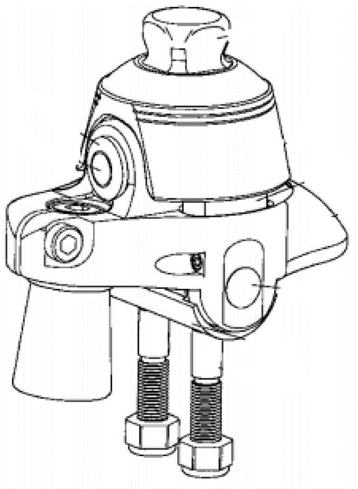
[0040] image 3It is a prosthetic ankle joint with four passive degrees of freedom in this embodiment, which includes a tibial part 1, a spherical hinge structure 3, 10, a tibial shock-absorbing torsion spring 2, a sole plate 5 and a return spring device.

[0041] The spherical joint structure is composed of two parts, including the spherical joint body 10 and the spherical joint bowl 3, which form a revolving pair, so the spherical joint body 10 can realize three degrees of freedom of rotation. The adjustment rod 9 is fixedly connected with the above-mentioned spherical joint sphere 10 by welding, the spherical joint sphere 10 is located in the middle of the adjustment rod 9, and the adjustment rod 9 is divided into an upper adjustment rod 902 and a lower adjustment rod 901, and an upper adjustment rod 902 and a lower adjustment rod 902. One end of the rod 901 is respectively welded and fixed to the ball joint 10 . The upper adjustment rod 902 passes through the tibia 1 , an...

Embodiment 2

[0049] Figure 4 , 5 . 6 is another prosthetic ankle joint with four passive degrees of freedom. The difference between this embodiment and Embodiment 1 is that the ball bowl of the ball joint structure in Embodiment 1 is divided into two parts. In addition, the ball joint bracket 4 The connection and the structure thereof are all different with the sole plate 5.

[0050] Such as Figure 5 , as shown in 6, the tibia 1 is divided into two parts, the tibial connecting rod 101 and the spring connecting shaft 102 . The tibial connecting rod 101 is connected with the knee joint of the whole prosthesis, and the spring connecting shaft 102 is connected with the tibial shock-absorbing torsion spring 2 . The tibial shock-absorbing torsion spring is sleeved on the spring connecting shaft 102, and the spring connecting shaft 102 has a hole in the radial direction, and the end of the tibial shock-absorbing torsion spring is inserted into the above-mentioned hole. The spring connecting...

Embodiment 3

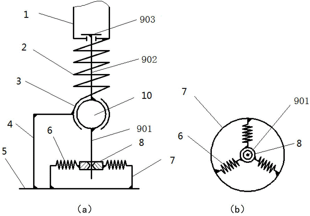
[0056] Such as Figure 9 and 10 Shown is an elastic rubber end cap, which is used to replace the return spring set in the above implementation example. The elastic rubber end cap is directly sleeved on the adjusting rod 9, and the movement of the adjusting rod 9 is directly restrained without using the adjusting sleeve 8 to restrict the movement of the adjusting rod 9. When the adjustment rod 9 is deflected due to the rotation of the spherical hinge sphere 10, it must overcome the elastic force of the elastic rubber end cap.

[0057] Such as Figure 9 and 10 As shown, a through hole is drilled in the center of the elastic rubber end cap, and the diameter is consistent with the adjustment rod 9, and the adjustment rod 9 coaxially passes through the center through hole. The elastic rubber end cap is installed on the circular support 7, and the two are connected by screws, and the circular support 7 is fixedly connected with the rear sole 501 and the rear sole pad 503 by scre...


PUM


Abstract

The invention discloses an artificial limb ankle, which comprises a regulating rod, a spherical hinge and a reset component, wherein one end of the regulating rod is connected with a shin bone in a relatively moving mode; the other end of the regulating rod is arranged on a foot bottom plate and used for connecting the shin bone with the foot bottom plate; the spherical hinge comprises a spherical bowl and a sphere which relatively rotates in the spherical bowl; the sphere is fixedly arranged in the middle of the regulating rod; the spherical bowl is fixed on the foot bottom plate through a spherical hinge bracket; the reset component comprises a shin bone damping torsion spring and a reset disk; the shin bone damping torsion spring is mounted on the regulating rod between the shin bone and the sphere in a sleeving manner; the reset disk is fixed on the foot bottom plate and mounted at the lower end of the regulating rod in a sleeving manner; and a restoring force is provided for multidirectional motion of the ankle joint by the reset component, so the ankle joint can automatically return. The four passive degrees of freedom of the artificial limb ankle joint are realized by the spherical hinge structure, and the restoring force is provided for the rotating degree of freedom by the shin bone damping torsion spring and a reset spring group, so that the ankle joint maintains stable when the artificial limb is in the support phase, and the ankle joint has damping and buffering functions.

Description

technical field [0001] The invention relates to an artificial limb used by amputee patients, in particular to an artificial limb ankle joint, which belongs to the technical field of rehabilitation engineering. Background technique [0002] As an important part of the lower limb joints of the human body, the ankle joint needs greater flexibility in movement, and it needs to meet the rotation degrees of freedom in three directions to adapt to the requirements of various gaits. These three rotational degrees of freedom are described as: dorsiflexion-extended flexion; varus-valgus; and the angle between the forward line of the sole. However, for thigh amputee patients, it may not be a good thing to have more degrees of freedom in the prosthetic ankle joint, because thigh amputee patients have lost their knee joints, and it is difficult to control the ankle joint with multiple degrees of freedom, which will easily lead to unstable support of the ankle joint, thus Causes the wear...

Claims


Application Information

Patent Timeline
Patent Type & Authority Patents(China)
IPC IPC(8): A61F2/66
Inventor 李小平贺鑫陈学东
Owner HUAZHONG UNIV OF SCI & TECH
Why Eureka
Try Eureka