Hydraulic cylinder

A technology for hydraulic cylinders and cylinders, which is applied in the field of piston rod anti-rotation mechanisms, and can solve problems such as inability to adjust the solution, difficulty in adjusting the piston rod and cylinder, and inability to adjust the load state

Active Publication Date: 2013-02-27
HUNAN TELI HYDRAULIC
View PDF8 Cites 14 Cited by
  • Summary
  • Abstract
  • Description
  • Claims
  • Application Information

AI Technical Summary

Problems solved by technology

[0004] The above-mentioned existing anti-rotation technologies all fix the radial angle between the piston rod and the cylinder body to prevent the piston rod from appearing in a linear motion while additional rotation. The disadvantage is that once the hydraulic cylinder is assembled, if it needs to Adjusting the angle of the piston rod to the cylinder will become very difficult, especially figure 1 , figure 2 and image 3 The program cannot be adjusted at all, Figure 4 The scheme also needs to remove some parts of the hydraulic cylinder before adjustment can be made, and it cannot be adjusted under load

Method used


Image

  • Hydraulic cylinder
  • Hydraulic cylinder
  • Hydraulic cylinder

Examples


Embodiment Construction

[0038] It should be noted that the features in the various embodiments of the present invention may be combined with each other in the absence of explicit limitation or conflict. The present invention will be described in detail below with reference to the accompanying drawings and examples.

[0039] In order to overcome the defects of the hydraulic cylinder in the prior art, the present invention provides an improved hydraulic cylinder and a hydraulic cylinder with the same.

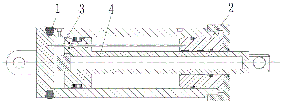
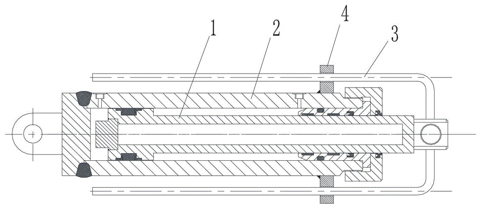
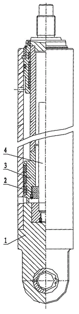
[0040] Figure 5 is a structural schematic diagram of a hydraulic cylinder according to an embodiment of the present invention, Figure 6 is along Figure 5 The sectional view of the A-A line only shows the guide block and the guide rod.

[0041] Such as Figure 5 As shown, the cylinder barrel 3 of the hydraulic cylinder in this embodiment is a round tube with an inner hole that has been precisely machined, and the outer circles of both ends are processed with external threads for connection, so as ...


PUM


Abstract

The invention relates to a hydraulic cylinder. The hydraulic cylinder comprises a cylinder barrel and a piston rod, wherein the piston rod is positioned in the cylinder barrel and is provided with a guide hole. The hydraulic cylinder further comprises a guide rod and a locking mechanism, wherein the guide rod is in match with the guide hole in the piston rod in order to limit the piston rod to rotate relatively to the guide rod; and the locking mechanism is used for controlling the guide rod and the piston rod to switch between a locking state in which the cylinder barrel can not relatively rotate and an unlocking state in which the cylinder barrel can relatively rotate. According to the technical scheme, the piston rod can be prevented from rotating under the combined action of the piston rod, the guide rod and the locking mechanism; the locking mechanism can be switched between the locking state and the unlocking state; and once the locking mechanism is in the unlocking state, the angle of the piston rod can be conveniently adjusted, so that the purpose of preventing the piston rod from rotating can be realized, and the angle position of the piston rod can be randomly adjusted.

Description

technical field [0001] The invention relates to a hydraulic cylinder, in particular to a piston rod anti-rotation mechanism in the hydraulic cylinder. Background technique [0002] At present, when ordinary hydraulic cylinders are stretching, due to reasons such as load eccentricity and uneven circumferential fit, the piston rod will produce a certain amount of rotation when it moves, resulting in a linear motion combined with rotation. When the piston rod is installed without coupling constraints due to work requirements, but it is necessary to output precise linear motion without rotation, the anti-rotation of the piston rod will become very important. [0003] At present, the anti-rotation of the hydraulic cylinder is mainly realized by two structures, the built-in anti-rotation and the external anti-rotation. The built-in anti-rotation device is generally such as figure 1 As shown, a guide rod 3 is set between the cylinder bottom 1 and the guide sleeve 2, and a hole is...

Claims


Application Information

Patent Timeline
Patent Type & Authority Applications(China)
IPC IPC(8): F15B15/14F15B15/20
Inventor 莫枭左美燕魏静
Owner HUNAN TELI HYDRAULIC
Why Eureka
Try Eureka