Oil filling nozzle
A technology of oiling nozzles and ball joints, which is applied in the direction of engine components, delivery pipes/joints, engine lubrication, etc., can solve the problems of abnormal wear of mechanical parts, inconvenient refueling, blockage of oil injection ports, etc., to achieve good adaptability and convenience The effect of oil injection
- Summary
- Abstract
- Description
- Claims
- Application Information
AI Technical Summary
Problems solved by technology
Method used
Image

Examples
Embodiment Construction
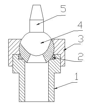
[0008] A grease nozzle, which includes a fixed pipe (1), a sealing ring (2), a bowl-shaped cover (3), a ball joint (4), and a grease nozzle (5). The upper port of the fixed pipe (1) is provided with a A spherical ball joint (4), a sealing ring (2) is arranged between the ball joint (4) and the fixed tube (1), and the ball joint (4) is fixed on the fixed tube (1) through a bowl-shaped cover (3) At the port part, the ball joint (4) has a degree of freedom of movement between the bowl-shaped cover (3) and the fixed pipe (1), and the ball joint (4) is fixed with a grease nozzle (5). (5) Connect with the middle hole of the fixed pipe (1) through the middle hole of the ball joint (4).
PUM
 Abstract
Description
Claims
Application Information
 - R&D
- Intellectual Property
- Life Sciences
- Materials
- Tech Scout
- Unparalleled Data Quality
- Higher Quality Content
- 60% Fewer Hallucinations
Browse by: Latest US Patents, China's latest patents, Technical Efficacy Thesaurus, Application Domain, Technology Topic, Popular Technical Reports.
© 2025 PatSnap. All rights reserved.Legal|Privacy policy|Modern Slavery Act Transparency Statement|Sitemap|About US| Contact US: help@patsnap.com