Electro-thermal-driven micro-electro-mechanical comb tooth mechanism for regulating variable intervals of teeth

An electrothermal drive and tooth gap technology, which is applied in the direction of microstructure devices composed of deformable elements, microstructure technology, microstructure devices, etc., can solve the problems of wasting driving force, weak sensor detection signals, and increased gaps, etc. problem, to achieve the effect of increasing the signal amplitude detected by the sensor, increasing the detection sensitivity, and expanding the scope of application

Inactive Publication Date: 2013-03-06
SOUTHEAST UNIV
View PDF5 Cites 10 Cited by
  • Summary
  • Abstract
  • Description
  • Claims
  • Application Information

AI Technical Summary

Problems solved by technology

Since the gap between the comb teeth of the traditional structure is immutable and cannot be made very small due to the limitation of the process, the sensing detection signal generated by the micro-electromechanical vibration is also very weak
[0004] Some researchers have proposed a comb structure with adjustable gaps on one side, but this structure has the following two main disadvantages: because the comb teeth are usually a multi-pair structure, th

Method used


Image

  • Electro-thermal-driven micro-electro-mechanical comb tooth mechanism for regulating variable intervals of teeth
  • Electro-thermal-driven micro-electro-mechanical comb tooth mechanism for regulating variable intervals of teeth
  • Electro-thermal-driven micro-electro-mechanical comb tooth mechanism for regulating variable intervals of teeth

Examples


Embodiment Construction

[0024] The present invention will be further described below in conjunction with the accompanying drawings.

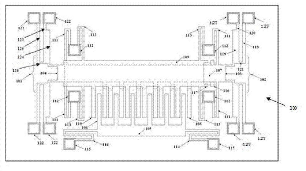
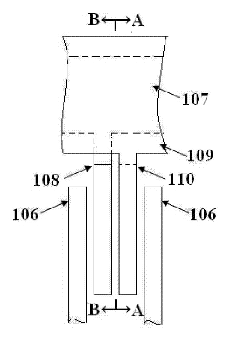
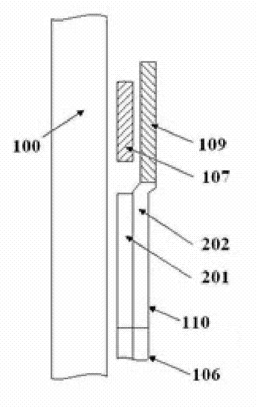
[0025] Such as Figure 1 to Figure 4 As shown, the micro-electromechanical comb tooth mechanism of the present invention, which is electrothermally driven to adjust the tooth gap, includes a left-moving electrothermal actuator 102, a right-moving electrothermal actuator 101, and a fixed tooth consisting of a left-moving fixed tooth 103 and a right-moving fixed tooth 104. , a movable tooth, four first anchor regions 112 and an insulating substrate 100 . The left-moving electrothermal actuator 102 is connected to one end of the left-moving fixed tooth 103 , and the two ends of the left-moving fixed tooth 103 are respectively connected to the first anchor area 112 . The right-moving electrothermal actuator 101 is connected to one end of the right-moving fixed tooth 104 , and the two ends of the right-moving fixed tooth 104 are respectively connected to the first anchor a...


PUM


Abstract

The invention discloses an electro-thermal-driven micro-electro-mechanical comb tooth mechanism for regulating variable intervals of teeth. The electro-thermal-driven micro-electro-mechanical comb tooth mechanism comprises a left-shift electrothermal actuator, a right-shift electrothermal actuator, a fixed tooth, a moving tooth, four first anchor regions and an insulating substrate, wherein the fixed tooth consists of a left-shift fixed tooth and a right-shift fixed tooth; the left-shift electrothermal actuator is connected with one end of the left-shift fixed tooth, and the two ends of the left-shift fixed tooth are respectively connected to the first anchor regions; the right-shift electrothermal actuator is connected with one end of the right-shift fixed tooth, and the two ends of the right-shift fixed tooth are respectively connected to the first anchor regions; the left-shift fixed tooth comprises a first wide beam, a left-shift comb tooth and four first folding beams; the right-shift fixed tooth comprises a first wide beam, a right-shift comb tooth and four second folding beams; the moving tooth comprises a quality block, a moving tooth comb tooth, two second anchor regions and two third folding beams; and a left-shift stop block is arranged on the first wide beam, and a right-shift stop block is arranged on the second wide beam. Under the driving of an electrothermal driving force, the micro-electro-mechanical comb tooth mechanism regulates the intervals of the teeth to enable a signal generated by micro-electro-mechanical vibration to be strong.

Description

technical field [0001] The invention belongs to the technical field of micro-electro-mechanical system structure, and in particular relates to a micro-electro-mechanical comb tooth mechanism for adjusting tooth gaps by electrothermal driving. Background technique [0002] Comb structures are widely used in MEMS, for example, resonators, accelerometers, angular velocity meters, gyroscopes, etc. The traditional comb structure consists of paired fixed teeth and movable teeth. The fixed teeth and movable teeth are arranged at intervals and usually have many pairs. In the traditional structure, the fixed teeth remain in a static state without longitudinal and lateral displacement, while the movable teeth usually move in the form of vibration under the action of external force, and the direction of motion is along the length of the teeth. [0003] Due to the limitation of machining accuracy, the gap between the fixed tooth and the movable tooth in the comb tooth structure cannot ...

Claims


Application Information

Patent Timeline
IPC IPC(8): B81B3/00
Inventor 李伟华浦烜周再发黄庆安
Owner SOUTHEAST UNIV
Why Eureka
Try Eureka