Signal enhancing structure and mobile multimedia broadcasting device

A mobile multimedia and signal enhancement technology, applied in the field of electromagnetic waves, can solve the problems of multiple devices, increase the signal strength of the transmitter, and fail to achieve the ideal signal reception effect, so as to improve the antenna signal receiving ability, improve the antenna signal receiving ability, The effect of good audio-visual effects

Active Publication Date: 2013-03-06
KUANG CHI INST OF ADVANCED TECH
View PDF7 Cites 1 Cited by
  • Summary
  • Abstract
  • Description
  • Claims
  • Application Information

AI Technical Summary

Problems solved by technology

[0002] With the development of society, the application of electromagnetic waves is becoming more and more extensive. In order to receive electromagnetic waves, antennas are usually installed on the device. Some devices use the form of external antennas, which can receive signals that basically meet the requirements, while some devices use built-in antennas. The form of the antenna will often cause poor signal, and the improved design of the antenna cannot achieve the ideal signal reception effect; the external antenna also needs better signal reception effect
Now, the methods to improve the lack of signal received by the antenna are mostly to increase the signal strength of the transmitter, or build more base stations, which will cause a lot of equipment investment, and will cause more and more serious electromagnetic wave pollution to nature
[0003] The above problems are more prominent on mobile wireless devices, and some mobile devices are not suitable for using external antennas, and built-in antennas cannot meet people's needs. In addition to increasing the density of base station construction and improving the signal transmission strength of transmitters In addition, there is still no good solution to this problem

Method used


Image

  • Signal enhancing structure and mobile multimedia broadcasting device
  • Signal enhancing structure and mobile multimedia broadcasting device
  • Signal enhancing structure and mobile multimedia broadcasting device

Examples


Embodiment Construction

[0021] The present invention will be further described below in conjunction with the accompanying drawings and specific embodiments.

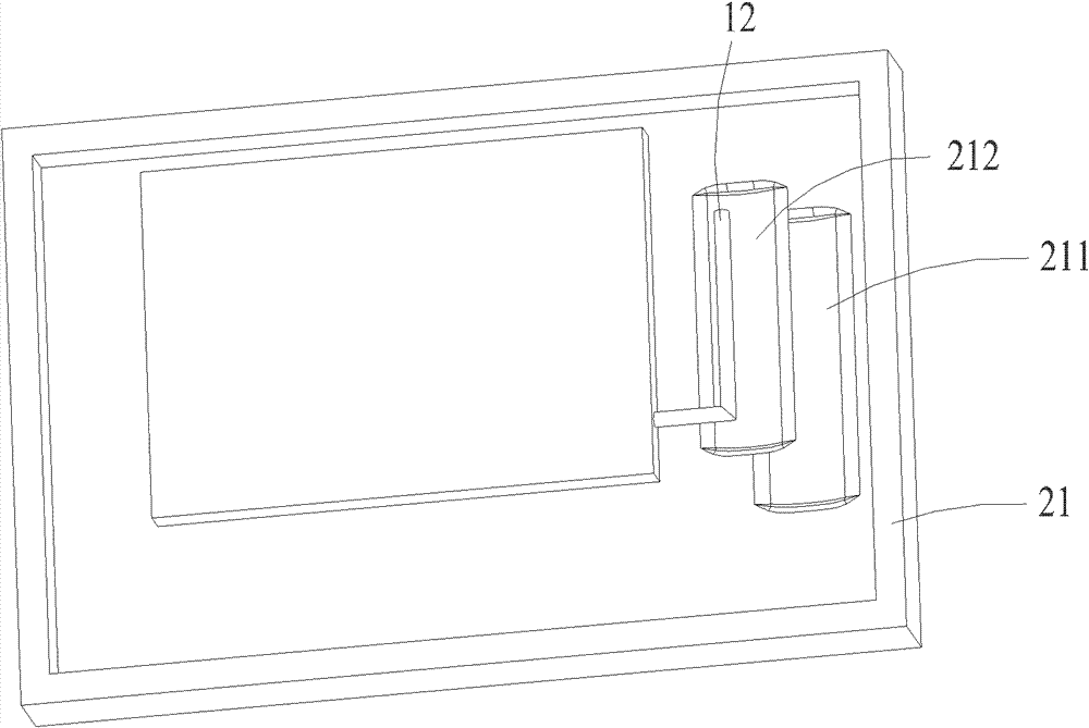
[0022] figure 1 Shown is a schematic diagram of a signal enhancement structure and the device where it is located. The inner surface of the housing 21 of the device is provided with a groove 211. The groove has a curved surface that bends inwardly of the housing 21. The curved surface is a cylindrical surface. A metal foil 212 is fixed on the groove 211, and the shape of the metal foil 212 is the same as that of the groove 211. The antenna 12 is set in a direction away from the curved surface of the metal foil 212, and the metal foil 212 is injected into the metal foil 212 from the direction of the antenna 12. Under the effect of the curved surface of the metal foil 212, the electromagnetic signal converges towards the antenna 12, which increases the strength of the signal received by the antenna 12.

[0023] figure 1 Only the case where the ...


PUM


Abstract

The invention provides a signal enhancing structure. The signal enhancing structure is arranged in a device with an antenna; and the signal enhancing structure comprises a metal foil with a bent curved surface which is opposite to the antenna. The invention further provides a mobile multimedia broadcasting device; the device is mounted on a traffic tool and comprises a signal receiving and processing module, a display module and a fixing module, wherein a fixing plate of the fixing module is provided with a side wall with an arc surface and the metal foil which has the same shape as the side wall, so as to reflect a broadcasting signal to the antenna. Small change is made on the basis of a previous structure, and the antenna signal receiving capability is improved and the requirement of the device on the emission signal strength of an emitter is reduced; and meanwhile, the quantity of base stations is reduced and the signal enhancing structure has very good popularization meaning. The mobile multimedia broadcasting device adopting the signal enhancing structure can improve the antenna signal receiving capability of the device and obtains good visual and audio effects.

Description

technical field [0001] The invention belongs to the field of electromagnetic waves, relates to a structure for enhancing electromagnetic wave signals, and also relates to a mobile multimedia broadcasting device using the structure. Background technique [0002] With the development of society, the application of electromagnetic waves is becoming more and more extensive. In order to receive electromagnetic waves, antennas are usually installed on the device. Some devices use the form of external antennas, which can receive signals that basically meet the requirements, while some devices use built-in antennas. In the form of external antennas, the signal is often not good, and the ideal signal reception effect cannot be achieved through the improved design of the antenna; better signal reception effect is also required for external antennas. However, most of the methods to improve the lack of antenna reception signal are to increase the signal strength of the transmitter, or b...

Claims


Application Information

Patent Timeline
Patent Type & Authority Applications(China)
IPC IPC(8): H01Q15/16H01Q1/24H04N21/414
Inventor 刘若鹏徐冠雄吕晶李日照
Owner KUANG CHI INST OF ADVANCED TECH
Why Eureka
Try Eureka