
Clock protection method and clock protection device

A protection device and clock technology, applied in the field of communication, can solve problems such as high device aging rate, increased equipment cost failure points, and no solution proposed

Active Publication Date: 2013-03-06
ZTE CORP
View PDF5 Cites 2 Cited by
  • Summary
  • Abstract
  • Description
  • Claims
  • Application Information

AI Technical Summary

Problems solved by technology

However, the device aging rate of the first analog PLL or half-analog and half-digital PLL is relatively high, and failures often occur due to problems with PLL circuit components; second, whether the PLL circuit can achieve synchronization and simultaneously follow the lock The phase loop circuit is related to the clock source, and it is difficult to judge whether the clock needs to be switched simply from the operating state of the phase-locked loop; third, for the performance detection of the phase-locked loop circuit device, it is generally necessary to introduce a new detection circuit, which increases the cost and cost of the equipment. new failure point
To address these problems, no effective solutions have been proposed

Method used


Image

  • Clock protection method and clock protection device
  • Clock protection method and clock protection device
  • Clock protection method and clock protection device

Examples


Embodiment Construction

[0026] Hereinafter, the present invention will be described in detail with reference to the drawings and examples. It should be noted that, in the case of no conflict, the embodiments in the present application and the features in the embodiments can be combined with each other.

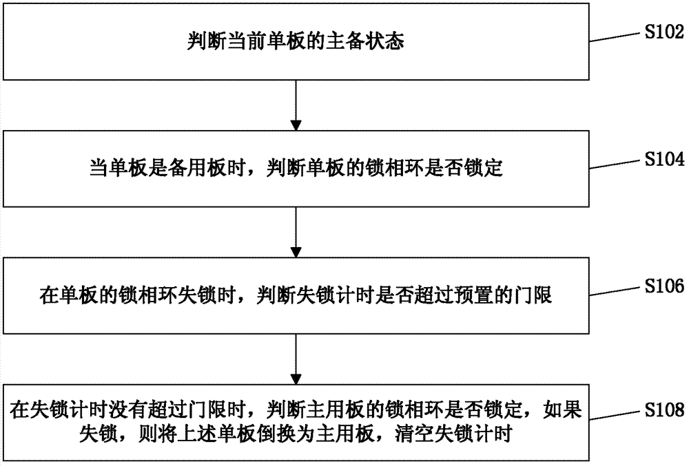
[0027] figure 1 is a flowchart of a clock protection method according to an embodiment of the present invention. like figure 1 As shown, the clock protection method according to the embodiment of the present invention includes:

[0028] Step S102, judging the active and standby status of the current single board;

[0029] Step S104, when the single board is a standby board, it is judged whether the PLL of the single board is locked;

[0030] Step S106, when the phase-locked loop of the single board is out of lock, it is judged whether the out-of-lock timing exceeds a preset threshold;

[0031] Step S108, when the out-of-lock time does not exceed the threshold, it is judged whether the phase-lock...


PUM


Abstract

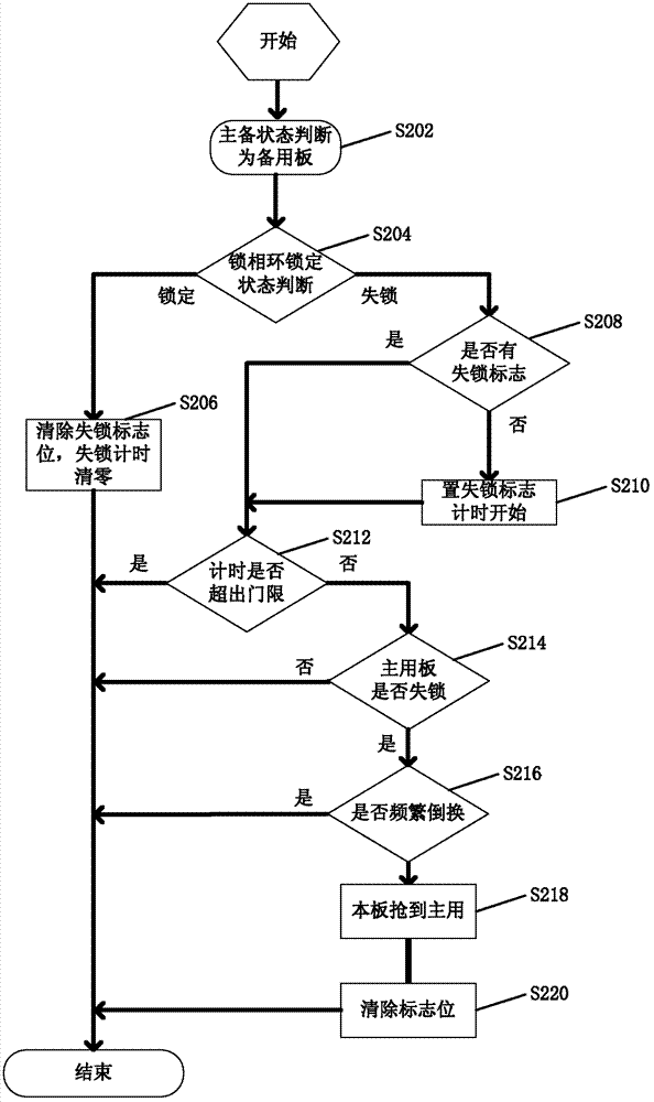
The invention discloses a clock protection method and a clock protection device. The clock protection method includes judging main and standby states of a current single board; judging whether a lock phase ring of the single board is locked or not when the single board is a standby board; judging whether lock loss timing exceeds a preset threshold value or not when the lock phase ring of the single board is in lock loss; when the lock loss timing is within the threshold, judging whether a lock phase ring of a main use board is locked or not, if in lock loss, switching the single board into the main use board, and emptying the lock loss timing. By the above technical scheme, the problems that whether to switch clock or not is difficult to judge by running states of the lock phase rings only in the prior art, and new equipment is required for detecting the lock phase rings are solved, judging whether a fault point is a lock phase ring circuit or a clock source is avoided, and protective switching when in asynchronous clock and service damages caused by lock loss of the lock phase rings is realized on the premise of no extra external equipment.

Description

technical field [0001] The present invention relates to the communication field, in particular to a clock protection method and device. Background technique [0002] For a synchronous communication system, it is very important to achieve clock synchronization between devices. Current devices usually use a 1+1 or 1:1 hot backup interlock clock scheme. Switch to the standby clock to ensure clock synchronization and reduce service damage. [0003] General equipment uses a phase-locked loop circuit to track and synchronize the external clock. However, the device aging rate of the first analog PLL or half-analog and half-digital PLL is relatively high, and failures often occur due to problems with PLL circuit components; second, whether the PLL circuit can achieve synchronization and simultaneously follow the lock The phase loop circuit is related to the clock source, and it is difficult to judge whether the clock needs to be switched simply from the operating state of the phas...

Claims


Application Information

Patent Timeline
Patent Type & Authority Applications(China)
IPC IPC(8): H04L12/24
CPCG06F3/00H03L7/06
Inventor 严婕
Owner ZTE CORP
Learn More