
Sliding type bearing assembly
A sliding, component technology, applied in the direction of support structure installation, rack/frame structure, etc., can solve the problems of high strength requirements of slide rails, inconvenient operation, bending deformation of slide rails, etc.
- Summary
- Abstract
- Description
- Claims
- Application Information
AI Technical Summary
Problems solved by technology
Method used
Image

Examples
Embodiment Construction
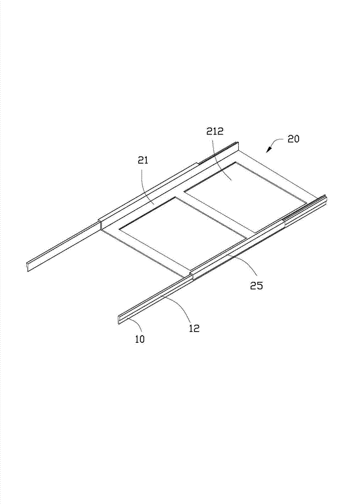
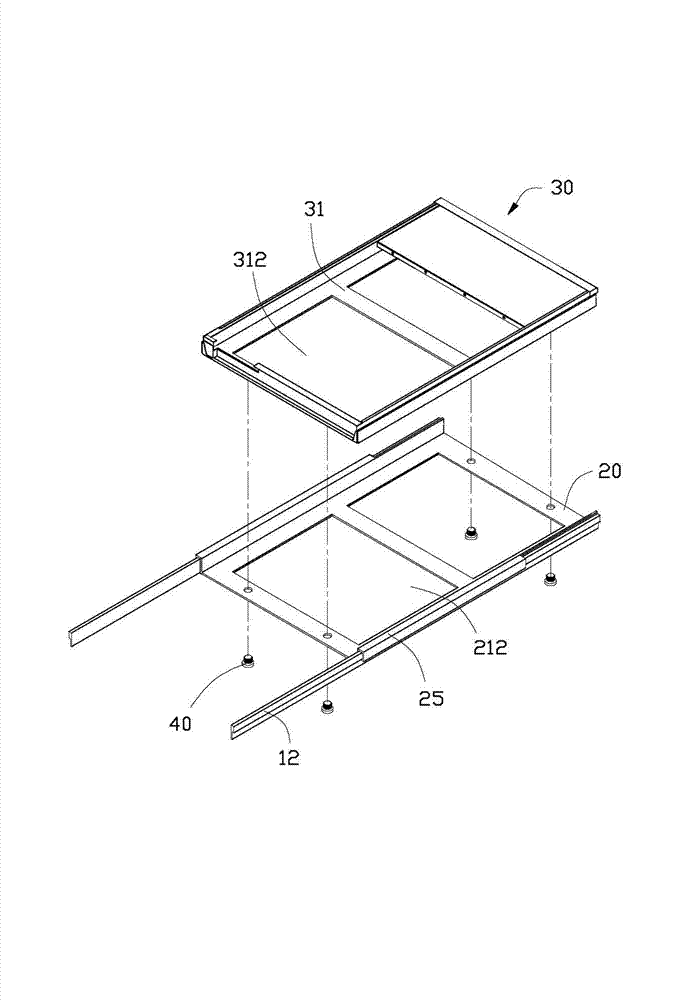
[0015] Please refer to Figure 1 to Figure 3 , the first preferred embodiment of the sliding bearing assembly of the present invention is used to support a server 30 . The sliding bearing assembly includes two slide rails 10 and a tray 20 .
[0016] The server 30 has a bottom wall 31 . The bottom wall 31 defines two spaced protrusions 312 downwards.
[0017] Each slide rail 10 is in the shape of a strip, and a protruding strip 12 protrudes along the length direction of the slide rail 10 on one side of the upper portion.
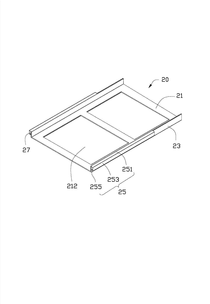
[0018] The tray 20 is integrally stamped and formed by a metal plate, which includes a bottom plate 21, two side walls 23 vertically extending upward from both sides of the bottom plate 21, and two sliding arms extending outward from the top of the two side walls 23 respectively. 25. One ends of the bottom plate 21 and the two sidewalls 23 protrude from the two sliding arms 25 . Two through slots 212 are defined on the bottom plate 21 at intervals. Each...
PUM
 Abstract
Description
Claims
Application Information