Door closer

A technology of door closers and shells, which is applied in the field of door closers and can solve problems such as high leakage loss and low spring force

Inactive Publication Date: 2013-03-06
DORMAKABA DEUT GMBH
View PDF8 Cites 6 Cited by
  • Summary
  • Abstract
  • Description
  • Claims
  • Application Information

AI Technical Summary

Problems solved by technology

[0020] In conclusion, it should be noted that the above control options of known door closers are not suitable for very small door closers with high operating pressures, because leakage losses are too high, or the spring force is too high for reliably keeping the control valve closed. Low

Method used


Image

  • Door closer
  • Door closer
  • Door closer

Examples


Embodiment Construction

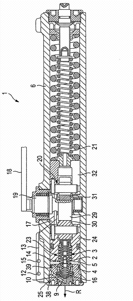
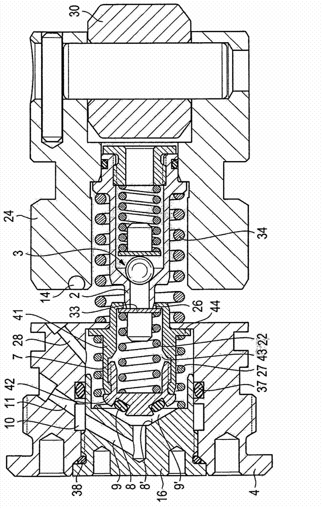
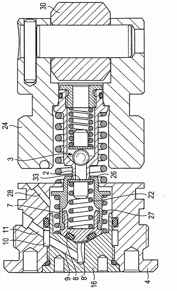
[0038] figure 1A door closer 1 according to the invention is shown in FIG. 1 , provided with a housing 6 . A drive device 20 is arranged in the housing 6, which device can be coupled via the closer shaft 19 and the arm assembly 18 to a door, which is not shown in detail in the figures. The drive device 20 is preferably configured as a cam drive with a cam disc 29 and with two rollers 30 and 31 which are arranged in a torque-proof manner on the shutter shaft 19 and which bear against the on the cam disc 29. In this case, the roller 30 is supported at the damping piston 24 , while the roller 31 is arranged at the drive piston 32 , which is in operative connection with the energy storage spring 21 , which is arranged in the housing 6 .

[0039] Furthermore, the door closer 1 has a hydraulic damper 23 . The device comprises a damping piston 24 arranged in the housing 6 , which is guided in the damping cylinder 5 . As mentioned above, the damping piston 24 is in operative conne...


PUM


Abstract

The invention relates to a door closer, comprising a door closer housing, a drive unit which can be coupled to a door by means of a door closer shaft and a linkage and is disposed in the door closer housing, and a hydraulic damping unit, which has a damping piston which is guided in a damping cylinder of the door closer housing and is operatively connected to the drive unit. Said damping piston cooperates with a first oil discharge channel associated with a rapid door closing movement and a second oil discharge channel associated with a slow door closing movement, wherein the first and second discharge channels are disposed one after the other and wherein the first discharge channel, as seen looking in the direction of movement of the damping piston, is disposed downstream of the second discharge channel.

Description

technical field [0001] The invention relates to a door closer according to the preamble of claim 1 . Background technique [0002] Most of the time, spring-hydraulic operated door closers are utilized for controlled closing of door systems. During a manual opening operation, the door closer shaft is rotated via the arm assembly and furthermore the energy storage spring is preloaded via the drive in the door closer. [0003] For the closing operation, the stored energy spring relaxes and pushes the door back into its starting position via the drive and arm assembly of the door closer without any external energy. [0004] In order not to make this operation happen suddenly and very quickly, the entire spring force of the accumulator in the door closer is almost completely absorbed by the hydraulic shock absorber. During the closing operation, due to the action of the piston surface, a hydraulic pressure corresponding to the spring force builds up in the pressure medium chamb...

Claims


Application Information

Patent Timeline
Patent Type & Authority Applications(China)
IPC IPC(8): E05F3/12E05F3/10
CPCE05F3/104E05Y2900/132E05F3/12
Inventor 福尔克·比内克
Owner DORMAKABA DEUT GMBH
Why Eureka
Try Eureka