Anti-slip shoes

A technology of anti-slip and anti-slip teeth, which is applied in the direction of footwear, soles, clothing, etc., can solve the problems of easy slipping and insufficient friction, and achieve the effect of reasonable overall structure design

Inactive Publication Date: 2013-03-13
栾亚萁
View PDF4 Cites 1 Cited by
  • Summary
  • Abstract
  • Description
  • Claims
  • Application Information

AI Technical Summary

Problems solved by technology

When climbing a mountain, due to the slope road surface, ordinary soles have insufficient friction and are easy to slip

Method used


Image

  • Anti-slip shoes

Examples


Embodiment Construction

[0014] In order to facilitate those skilled in the art to better understand the present invention, the present invention will be described in further detail below in conjunction with the accompanying drawings and specific embodiments, and the following description is only exemplary.

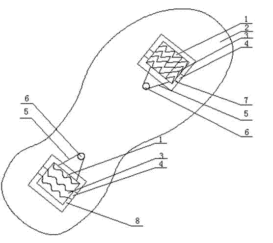
[0015] Reference attached figure 1 A kind of anti-slip shoes, comprising a sole 2, a front groove 7 is provided at the front of the sole 2, a rear groove 8 is provided at the rear of the sole, an anti-skid structure with the same structure is arranged in the front groove 7 and the rear groove 8, and the anti-skid structure It includes a rotating shaft 4, a flap 1 arranged on the rotating shaft 4, and an anti-slip tooth 3 located on the surface of the flap 1. The fixed shaft 6 is arranged behind the front groove 8, and the fixed shaft 6 is arranged in front of the rear groove 8. One side of the flap 1 Link to each other with fixed shaft 6 through connecting buckle 5.

[0016] The anti-skid teeth ...


PUM


Abstract

The invention aims to provide anti-slip shoes with a reasonable design, which can achieve an anti-slip effect in different places. The invention adopts the following technical scheme that the anti-slip shoes comprise shoe soles, wherein back grooves are formed at the back parts of the shoe soles; anti-slip structures which comprise rotary shafts, turnover plates arranged on the rotary shafts and anti-slip teeth positioned on the surfaces of the turnover plates are arranged in the back grooves; fixed shafts are arranged in front of the back grooves; and one side of each turnover plate is connected with the corresponding fixed shaft via a connecting buckle.

Description

technical field [0001] The invention relates to a shoe, in particular to a non-slip shoe, which belongs to the field of daily necessities. Background technique [0002] Ordinary soles mainly rely on the convex-concave structure arranged on the sole to play an anti-skid effect. After a long time, the convex-concave structure will not be able to achieve the anti-skid effect. For the road surface after snow, the anti-skid effect of ordinary convex-concave structure is not very good. When climbing a mountain, due to the sloping road surface, ordinary soles have insufficient friction and are prone to slipping. Contents of the invention [0003] The object of the present invention is to provide a reasonably designed anti-skid shoe, which can achieve anti-skid effects in different venues. [0004] In order to achieve the above object, the present invention adopts the following technical solutions: [0005] An anti-skid shoe, comprising a sole, a rear groove is provided at the ...

Claims


Application Information

Patent Timeline
Patent Type & Authority Applications(China)
IPC IPC(8): A43B13/22A43C15/02
Inventor 栾亚萁
Owner 栾亚萁
Why Eureka
Try Eureka