

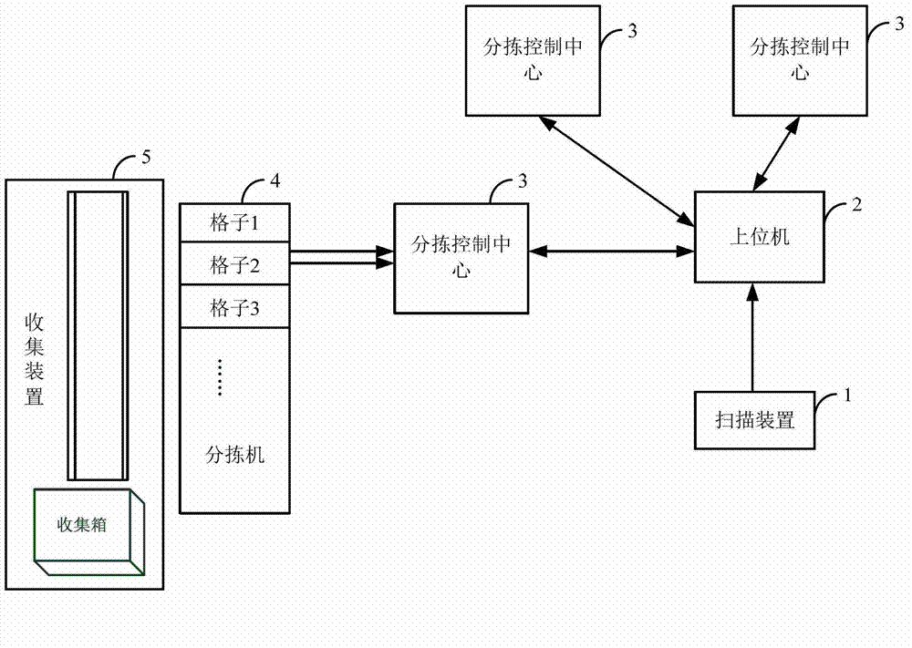
Flat mail sorting system
A sorting system and mail technology, applied in the field of flat mail sorting system, can solve the problems of low production efficiency and high labor cost, and achieve the effect of reducing labor cost, improving sorting speed, and high degree of intelligence
- Summary
- Abstract
- Description
- Claims
- Application Information
AI Technical Summary
Problems solved by technology
Method used
Image

Examples
Embodiment 1
[0044] Such as Figure 4 As shown, the stepping motor 41 directly drives the baffle 42, and the motor shaft 43 will directly bear the impulse from the mail in the grid 44, so the stepping motor 41 should have relatively large static torque when closing the baffle 42 without affecting For mail sorting speed, the rotation speed of the stepper motor 41 should be sufficient to meet the speed of 90 rotation angles in 1 second. It is better that the temperature rise of the stepper motor 41 does not exceed 60 degrees.
Embodiment 2
[0046]Such as Figure 5 As shown, this method mainly reduces the requirements on the motor, as long as the dynamic torque of the motor can move the baffle 51 and the static torque can maintain the state, the tension spring 52 needs to have sufficient length and tension. If space is to be saved, the height of the baffle plate can be selected as half of the lattice box, and if the baffle plate 51 needs to be the same as the height of the box body, it needs 2 times the space. There are sliding baffles on both sides of the mail baffle, and a toggle plate 54 should be installed on both sides of the motor shaft 53 .
Embodiment 3
[0048] Such as Image 6 As shown, in this mechanism, only the linkage rod 61 blocks the object from the rear portion of the lattice 63, and one end of the linkage rod 61 is fixed by the translation roller 62. When it is necessary to block the object, the fixed rod 64 and the motor 65 rotate synchronously, thereby driving one side of the linkage rod 61 to rise upward. The best way is to slot the grid box in the active area of the linkage rod 61, so that the impulse force received by the linkage rod 61 can be transmitted to the box for consumption, and the motor 65 is free from the impact of the impulse force. . Therefore, it is only necessary to use an ordinary motor, and the motor 65 is powered off at the highest point and the lowest point, so as to prevent the motor from heating and save energy. Image 6 The middle dotted line part represents the movement direction and track when the linkage rod 61 rises.
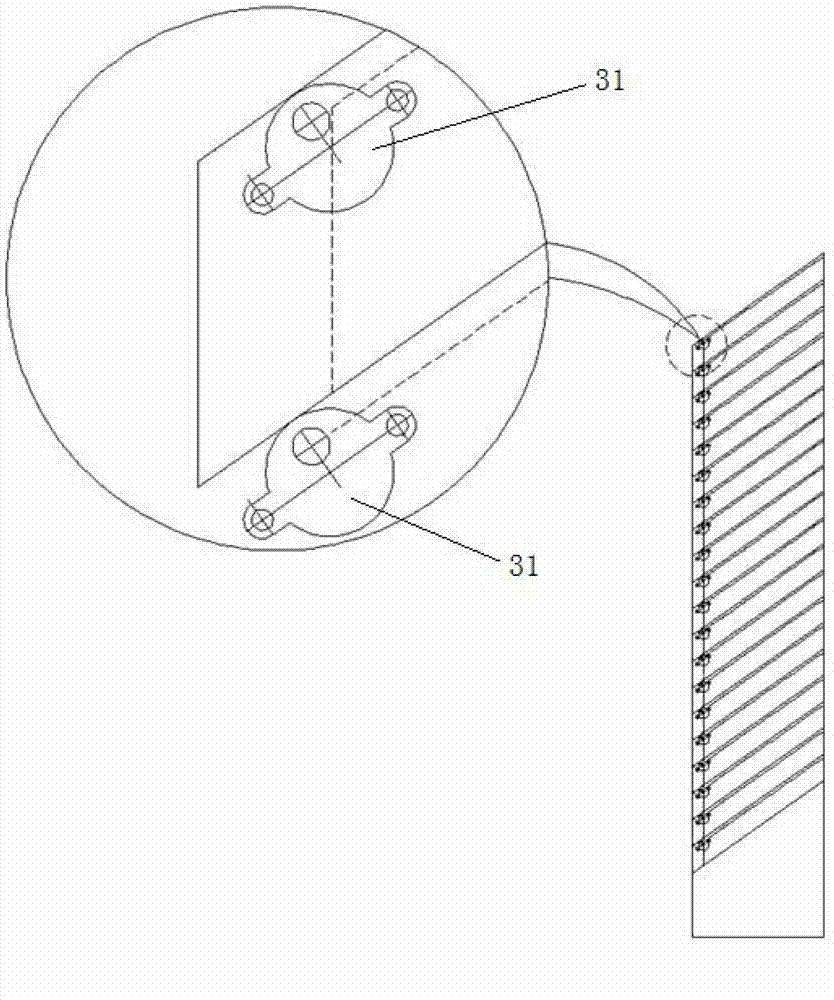
[0049] The structure of the sorting control center 3 is as follo...
PUM
 Abstract
Description
Claims
Application Information