

Multifunctional returning mechanism
A material return mechanism and multi-functional technology, applied in the field of pressure machinery, can solve the problems of complex structure, large space occupied by the cylinder, discomfort and other problems, and achieve the effect of overcoming the complex structure
Inactive Publication Date: 2013-03-13
董成刚
View PDF0 Cites 0 Cited by
- Summary
- Abstract
- Description
- Claims
- Application Information
AI Technical Summary
Problems solved by technology
[0005] Beneficial effects: due to the adoption of the above scheme, the material is returned by using the material return spring installed in the center hole of the worktable, which effectively overcomes the complex structure, difficult installation, and large space occupied by the cylinder in the existing material return device. and the disadvantages of using it on multi-position machines
Method used
View moreImage
Smart ImageViewing Examples

Examples
Embodiment Construction
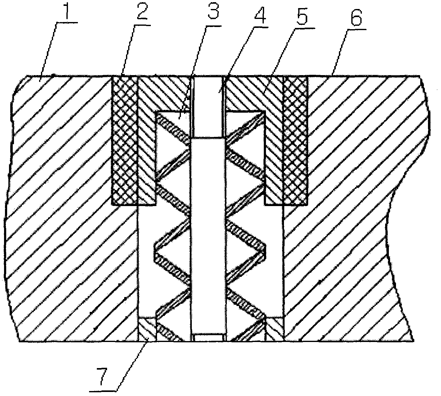
[0009] The multifunctional material return mechanism has a butterfly spring upper sleeve (5), and the butterfly spring upper sleeve (5) is installed on the upper part of the step hole of the workbench (1) through a lubricating bearing (2), and the two ends of the butterfly spring (3) Installed in the step hole of the butterfly spring lower sleeve (7), the positioning screw (4) is set in the hole of the butterfly spring (3), the upper end is fixed with the butterfly spring upper sleeve (5) by silk threads, and the lower end is lubricated Bearing is installed on the body (6).
Login to View More PUM
 Abstract
The invention relates to a multifunctional returning mechanism which is provided with an upper disc spring sleeve, wherein the upper disc spring sleeve is mounted on the upper part of a stepped hole of an operating platform through a lubricating bearing; the two ends of a disc spring are mounted in the stepped holes of a lower disc spring sleeve; a positioning screw rod is sleeved in a hole of the disc spring; the upper end of the positioning screw rod is fixed with the upper disc spring sleeve through a thread; and the lower end of the positioning screw rod is mounted on a machine body through the lubricating bearing. The scheme is adopted, so that athe returning spring mounted in a central hole of an operating platform plate is utilized to return the materials, and the defects of complex structure, difficulty in mounting, large space occupied by cylinders and unsuitability for multi-station machinery of the present returning device are effectively overcome.
Description
technical field [0001] The invention relates to a material return mechanism, in particular to a multifunctional material return mechanism, which belongs to the technical field of pressure machinery. Background technique [0002] At present, there are generally two types of material return devices for presses. One form is to install polyurethane plates or springs in the mold to achieve material return, and the other form uses cylinders to eject materials. However, due to the above two forms of material return The device has a complex structure, is difficult to install, and the cylinder occupies a large space, so it is not suitable for use on a multi-station machine. Contents of the invention [0003] The purpose of the present invention is to provide a multifunctional material return mechanism to overcome the above-mentioned defects in the existing material return device. [0004] The technical solution adopted by the present invention to achieve the above object is: the m...
Claims
Login to View More Application Information
Patent Timeline
 IPC IPC(8): B30B15/32
Inventor董成刚
Owner董成刚