
A multi-channel led constant current drive circuit

A constant current drive and circuit technology, applied in the electronic field, can solve the problems of complex circuit structure, large loss of current regulation circuit, large loss, etc., to overcome the complex circuit structure, simplify the circuit structure and the number of components, reduce circuit loss Effect

Active Publication Date: 2017-11-17
XIDIAN UNIV
View PDF10 Cites 0 Cited by
  • Summary
  • Abstract
  • Description
  • Claims
  • Application Information

AI Technical Summary

Problems solved by technology

The shortcomings of this circuit are: the circuit uses multiple voltage regulators to achieve the purpose of controlling the current sharing of multiple LED strings, the circuit structure is complex, the number of components is large, and the loss is large
The disadvantages of this circuit are: the circuit uses multi-channel current regulators to achieve the purpose of controlling the current sharing of multiple LED strings, the circuit structure is complex, and the loss is large; in order to make the multi-channel regulators work normally For the purpose of the current, the voltage drop on the multiplexer is usually a large value, usually the voltage drop on the current regulation circuit ranges from 0.5 to 1V, and the loss of the current regulation circuit is relatively large
The problem with the circuit disclosed in this paper is: the circuit uses multiple current regulators to achieve the purpose of controlling the current sharing of multiple LED strings, the circuit structure is complex, and the loss is large

Method used


Image

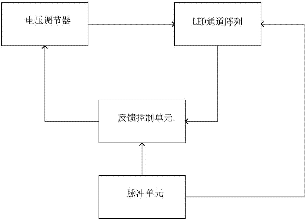
  • A multi-channel led constant current drive circuit
  • A multi-channel led constant current drive circuit
  • A multi-channel led constant current drive circuit

Examples


Embodiment Construction

[0021] The present invention will be described in detail below in conjunction with the accompanying drawings.

[0022] refer to figure 1 The unit of the present invention is described in detail.

[0023]The invention comprises a voltage regulator, an LED channel array and a feedback control unit, and the output end of the voltage regulator is connected with the first port of the LED channel array. The voltage regulator, the voltage regulator can be a step-up voltage regulator or a step-down voltage regulator, which is used to receive the feedback control signal and adjust the output voltage of the voltage regulator according to the feedback control signal. The first input port of the LED channel array is connected with the output terminal of the voltage regulator, the second input port of the LED channel array is connected with the output terminal of the pulse unit, and the output terminal of the LED channel array is connected with the first input terminal of the feedback con...


PUM


Abstract

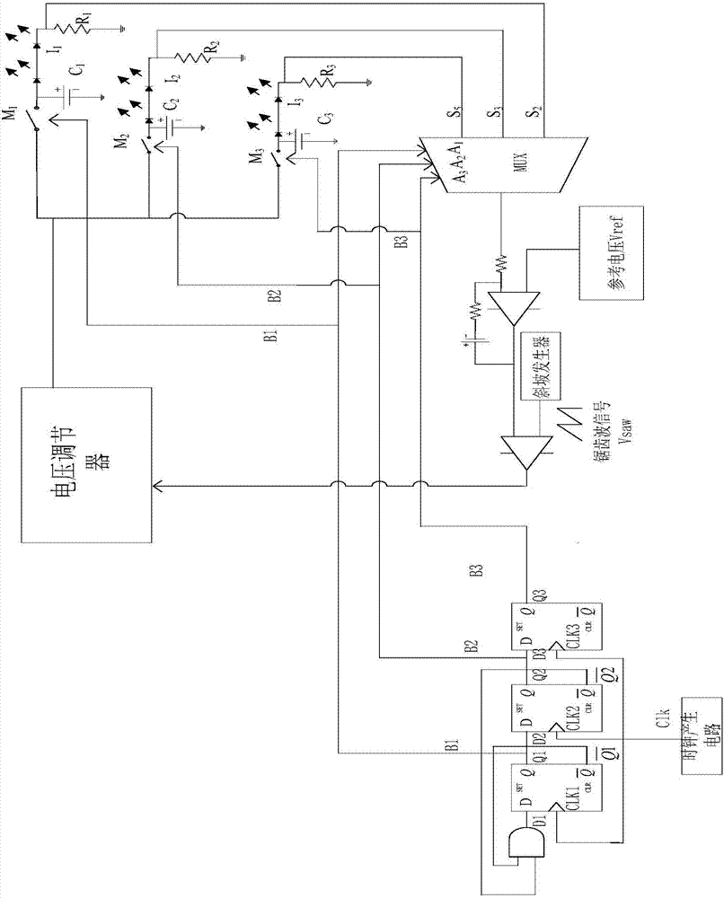
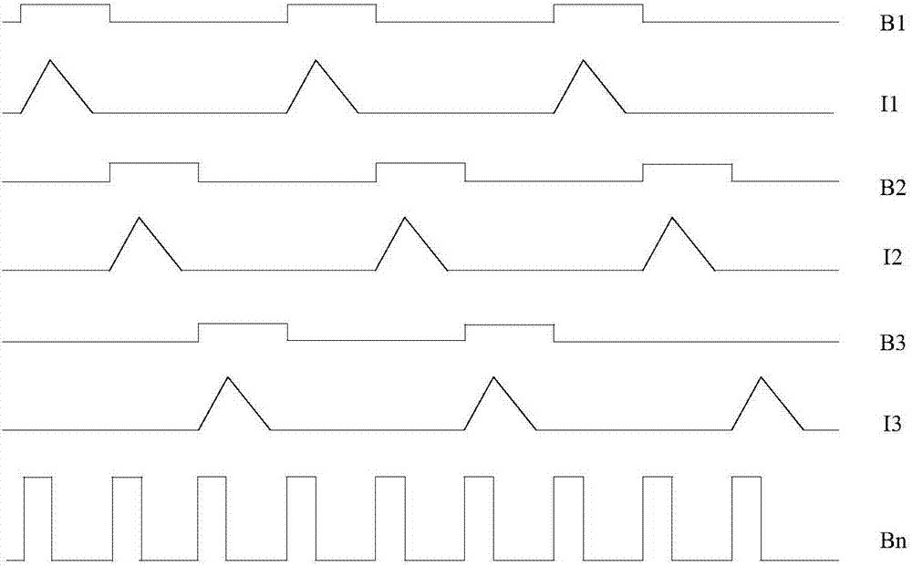
The invention discloses a multi-channel LED constant current drive circuit, which includes a voltage regulator, an LED channel array and a feedback control unit. The feedback control unit includes a multiplexer, an error amplifier and a comparator. The pulse unit selects the sampling voltage of one of the LED branches in time-sharing by controlling the multiplexer to input the feedback control circuit to generate a feedback control signal to control voltage regulation. To achieve the purpose of precisely controlling the current of each LED branch. By adopting an error amplifier and making the resistance value of the sampling resistor of each LED branch the same to realize the consistency of controlling the current and voltage of each LED branch. The invention realizes the purpose of time-division multiplexing the same feedback control circuit through the pulse circuit, and simplifies the number of feedback circuit elements and the circuit structure. The error amplifier reduces the voltage drop across the current regulation circuit, reducing circuit losses.

Description

technical field [0001] The invention belongs to the technical field of electronics, and further relates to a multi-channel LED constant current drive circuit in the technical field of power electronics. The invention can be used to realize multi-channel LED constant current driving. Background technique [0002] In lighting and backlight applications, multiple LED lamp strings are often used in parallel. Each LED lamp string includes one or more LED lamps connected in series. The luminous intensity of each LED lamp is determined by the current flowing through the LED lamp. Therefore, a current regulation circuit is used in the application to control the current flowing through the LED light string. At the same time, due to the differences in the characteristics of each LED light string itself, when the same current flows through each LED light string in practice, its conduction voltage drop will be different, so the current regulation circuits of different branches will wit...

Claims


Application Information

Patent Timeline
Patent Type & Authority Patents(China)
IPC IPC(8): H05B33/08H05B44/00
CPCH05B45/37Y02B20/30
Inventor 张艺蒙刘金金吕红亮汤晓燕张玉明
Owner XIDIAN UNIV
Learn More