Quick locking mechanism

A locking mechanism and fast technology, applied in the direction of locking fasteners, connecting components, mechanical equipment, etc., can solve problems such as thread damage, affecting locking function, and low locking efficiency

Active Publication Date: 2013-03-13
CHINA PRECISION ENG INST FOR AIRCRAFT IND AVIC
View PDF5 Cites 9 Cited by
  • Summary
  • Abstract
  • Description
  • Claims
  • Application Information

AI Technical Summary

Problems solved by technology

[0002] The usual locking between two parts is carried out by locking screws with ordinary threads. The screw 13 passes through the workpiece 14 to fix it on the workpiece 15, and a spring washer is added to prevent loo

Method used


Image

  • Quick locking mechanism
  • Quick locking mechanism
  • Quick locking mechanism

Examples


Embodiment Construction

[0011] The present invention will be described in detail below in conjunction with the accompanying drawings.

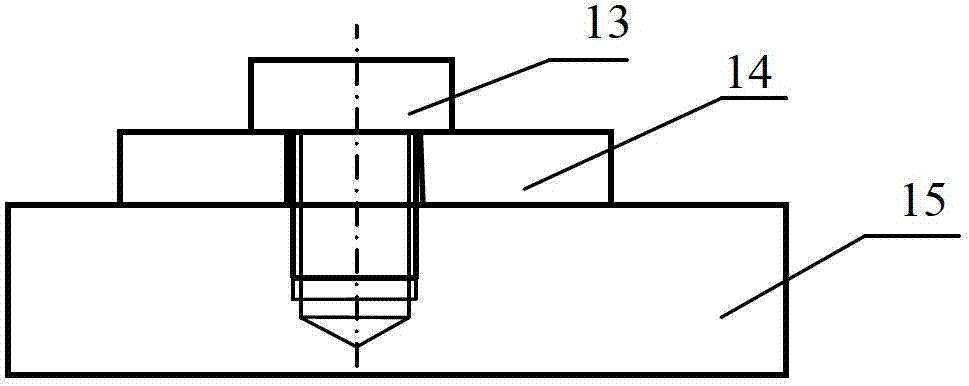
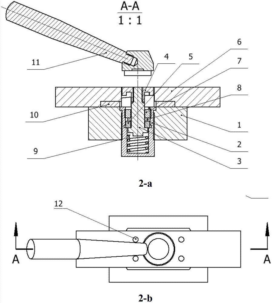
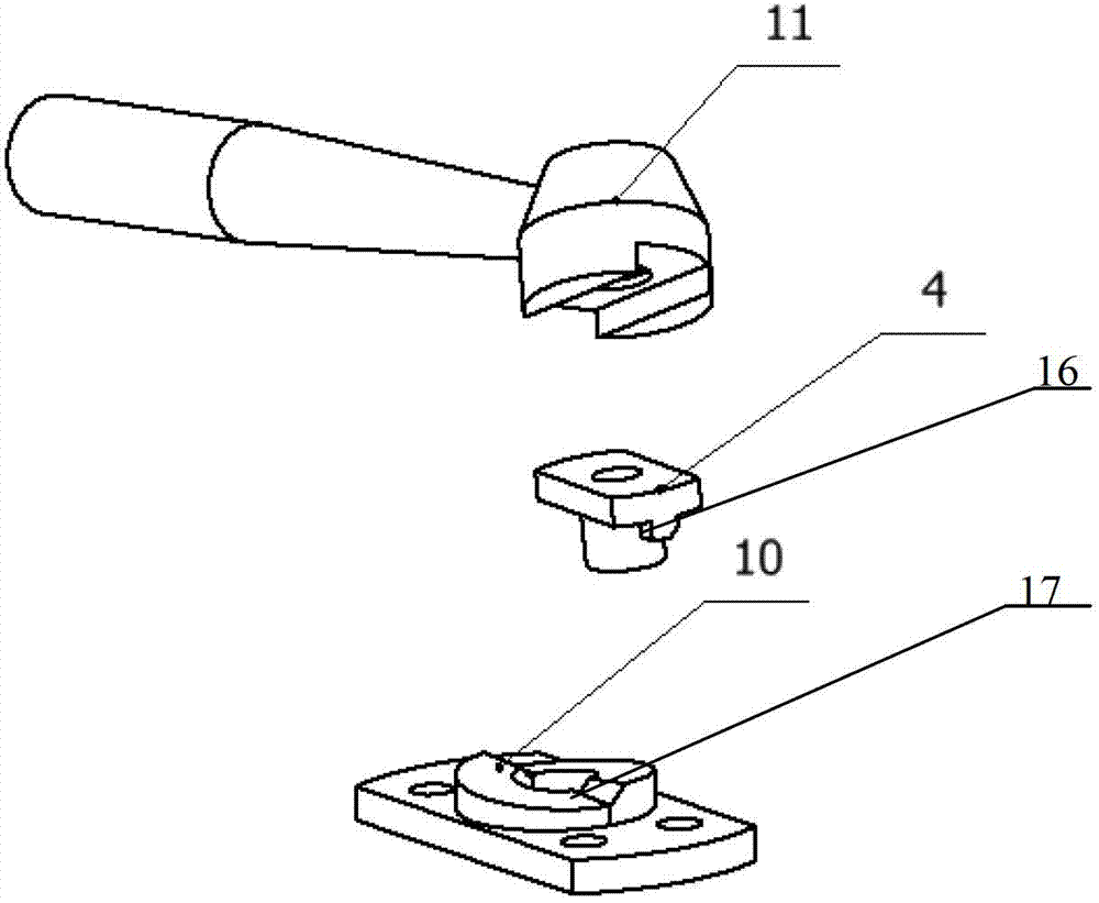
[0012] This structure is mainly composed of a locking sleeve 2, a locking shaft 3, a locking nut 4, and an oblique pressure block 10;

[0013] During the locking process of the lock nut 4 with the locking shaft 3 through the thread, it contacts with the oblique pressure block 10 with an inclined surface. The axial displacement during the locking process is the superposition of the spiral displacement and the rising displacement of the inclined surface. With anti-loose spring washer 8.

[0014] The oblique pressing block 10 is fixed on the workpiece B6 through the screw 12, and the locking sleeve 2 is fixed in the threaded hole of the workpiece A1 through the thread on its outer cylindrical surface;

[0015] A compression spring 9 is installed at the bottom of the center hole of the lock sleeve 2, and is supported on the lower end surface of the lock shaft 3. The cen...


PUM


Abstract

The invention relates to a connecting structure for quickly locking two parts, in particular to a quick locking mechanism. A locking structure combining an oblique plane and a locking thread is adopted, the quick locking of two workpieces to be locked is realized, and the quick locking mechanism is self-locked and anti-loose after being locked. In the quick locking mechanism, a compression spring is mounted under a locking shaft, the locking shaft rotates in the locking process, when the locking force is excessive due to misuse, the compression spring can play the role of preventing a locking nut from being deadly blocked in the screwing process, and the effect of protecting the thread is realized. The axial displacement of the whole quick locking mechanism in the locking process is the superposition of spiral displacement of the locking shaft and the oblique plane rising displacement of an oblique pressing block, and the locking efficiency is greatly improved; in the locking process, the lower surface of the locking nut presses the upper locking oblique plane of the oblique pressing block, with the effect of a spring gasket, the quick locking mechanism is self-locked and anti-loose after being locked; a special tool in the quick locking mechanism can take the effect of dismantling resistance and prevent the dismantling due to misoperation.

Description

technical field [0001] The invention relates to a connection structure capable of quickly locking two parts, in particular to a quick locking mechanism. Background technique [0002] The usual locking between two parts is carried out by locking screws with ordinary threads. The screw 13 passes through the workpiece 14 to fix it on the workpiece 15, and a spring washer is added to prevent loosening. However, this locking method , After repeated locking for many times, thread damage will occur, which will affect the locking function; and this locking method is low in locking efficiency because it only relies on screw locking. Contents of the invention [0003] The purpose of the present invention is to provide a fast locking mechanism with a thread that is not easy to be damaged and has high locking efficiency. [0004] The technical solution of the present invention is that the locking mechanism includes a locking sleeve 2, a locking shaft 3, a locking nut 4, a pressing bl...

Claims


Application Information

Patent Timeline
IPC IPC(8): F16B41/00F16B39/24
Inventor 张彬杨辉鲍龙祥李浩
Owner CHINA PRECISION ENG INST FOR AIRCRAFT IND AVIC
Why Eureka
Try Eureka