High-slip hydraulic coupler with multiple flow passages

A hydraulic coupling and multi-channel technology, applied in fluid transmission devices, belts/chains/gears, mechanical equipment, etc., can solve problems such as slow response, high motor power requirements, unfavorable savings, etc., to achieve protection and service life , improve economic efficiency, and solve overheating problems

Active Publication Date: 2013-03-13
YUEYANG HAIRUN ELECTRIC
View PDF10 Cites 0 Cited by
  • Summary
  • Abstract
  • Description
  • Claims
  • Application Information

AI Technical Summary

Problems solved by technology

[0003] At present, the slip devices of domestic supporting reels mainly include magnetic coupling type, torque motor type, friction type and frequency conversion type. The torque characteristic of the magnetic coupling type is relatively hard. When switching between retracting and unwinding cables, the cable tension changes greatly, which is not conducive to protection. Cable; the torque motor type reel responds slowly, and the power requirement of the motor is large, which is not conducive to saving; the frequency conversion type reel has many structures and supporting facilities, and the response is also slow

Method used


Image

  • High-slip hydraulic coupler with multiple flow passages
  • High-slip hydraulic coupler with multiple flow passages
  • High-slip hydraulic coupler with multiple flow passages

Examples


Embodiment Construction

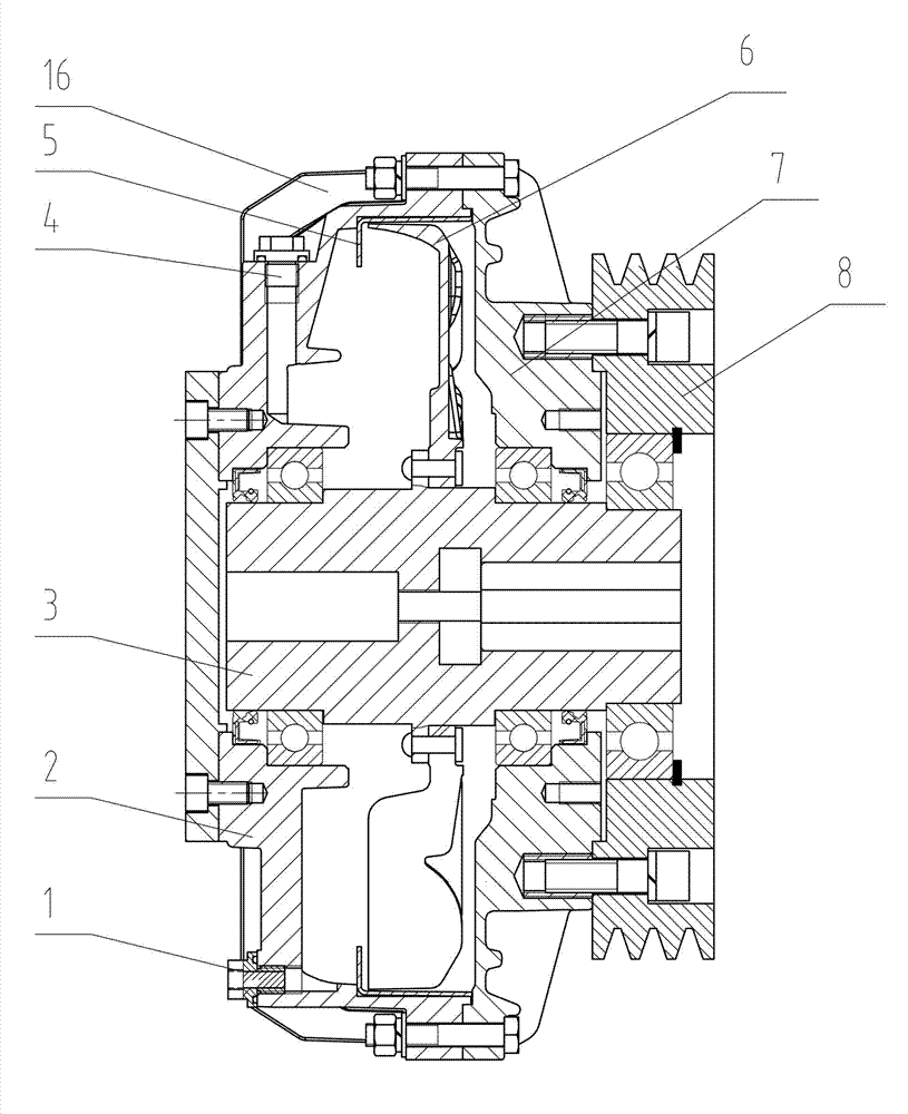
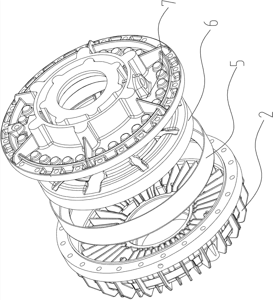
[0021] Depend on Figure 1 to Figure 11 It can be seen that the present invention includes a casing 7, a pump wheel 2 fixedly connected with the casing 7 and a turbine 6 corresponding to the pump wheel 2, the casing 7 is provided with an input pulley 8, the turbine 6 is fixedly connected with the output shaft 3, the input pulley 8, the casing 7 and the pump wheel 2 are connected as a whole, and the three are arranged on the output shaft 3 through bearings, which are characterized in that:

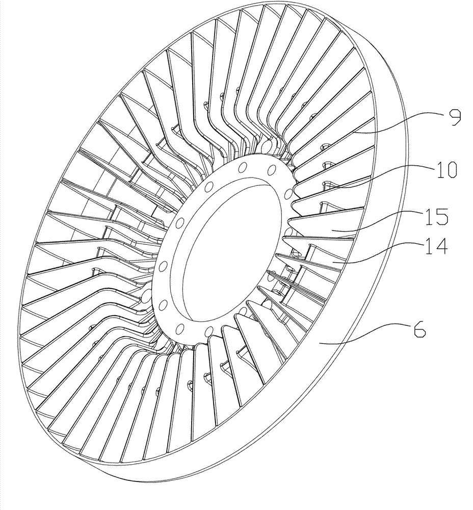
[0022] The inner side of the pump wheel 2 is a concave cavity, in which guide vanes 9 are arranged, and the inner cavity of the turbine 6 is also provided with guide vanes 9, and the turbine 6 is arranged in the concave cavity of the pump wheel 2, and the guide vanes on the inside of the two 9 corresponds to the setting, and a guide ring 5 is set between the pump wheel 2 and the turbine 6;

[0023] The above-mentioned guide vanes 9 are arranged at intervals to form a flow channel, and the ...


PUM


Abstract

The invention relates to a high-slip hydraulic coupler with multiple flow passages, which comprises a shell, a pump pulley fixedly connected with the shell and a worm wheel arranged corresponding to the pump pulley, wherein the shell is provided with an input belt pulley; the worm wheel is fixedly connected with an output shaft; the input belt wheel, the shell and the pump pulley are connected integrally and are arranged on the output shaft through a bearing. The high-slip hydraulic coupler with the multiple flow passages is characterized in that the inner side of the pump pulley is a sunken hollow cavity which is internally provided with guide vanes; the inner cavity of the worm wheel is also provided with guide vanes; the worm wheel is arranged in the sunken hollow cavity of the pump wheel; the guide vanes of the inner sides of the worm wheel and the pump pulley are arranged correspondingly; a guide ring is arranged between the pump pulley and the worm wheel; the guide vanes are arranged at intervals to form the flow passages; the inner side ends of the flow passage spaces are provided with flow baffle plates transversely or are not provided with the flow baffle plates; the flow passage on the pump pulley comprises a pump pulley main flow passage, a pump pulley auxiliary flow passage and a pump pulley assistant flow passage; and the flow passage on the worm wheel comprises a worm wheel main flow passage and a worm wheel auxiliary flow passage. The high-slip hydraulic coupler with the multiple flow passages can be adaptive to continuous use time of a cable of a cable drum, so that the problems of high frequency and high speed of the cable drum are solved; and the high-slip hydraulic coupler with the multiple flow passages is adjustable in torque and wide in application.

Description

technical field [0001] The invention relates to a torque-limiting hydraulic coupler in a hydraulic transmission device, in particular to a high-slip hydraulic coupler with multiple channels that meets the requirement of high slip and works continuously. Background technique [0002] With the development of the economy, the requirements for the frequency and speed of crane use in the logistics industry are getting higher and higher, and the operation frequency of the supporting cranes and other equipment such as lifting electromagnets, electro-hydraulic grabs, etc. will increase accordingly. , as its energy supply equipment, the cable reel must meet the following characteristics in order to serve the main equipment well: 1: Less wearing parts; 2: The torque characteristic when retracting and unwinding the cable is smooth without sudden changes. [0003] At present, the slip devices of domestic supporting reels mainly include magnetic coupling type, torque motor type, friction...

Claims


Application Information

Patent Timeline
Patent Type & Authority Applications(China)
IPC IPC(8): F16H41/04F16H41/24F16H41/30
Inventor 符建光刘彬
Owner YUEYANG HAIRUN ELECTRIC
Why Eureka
Try Eureka