

Detecting method for short dot position of cable
A detection method and short-circuit point technology, applied in the direction of fault location, etc., can solve the problems of complex test process and high test requirements, and achieve the effect of simple test principle and simple operation
- Summary
- Abstract
- Description
- Claims
- Application Information
AI Technical Summary
Problems solved by technology
Method used
Image


Examples
Embodiment Construction
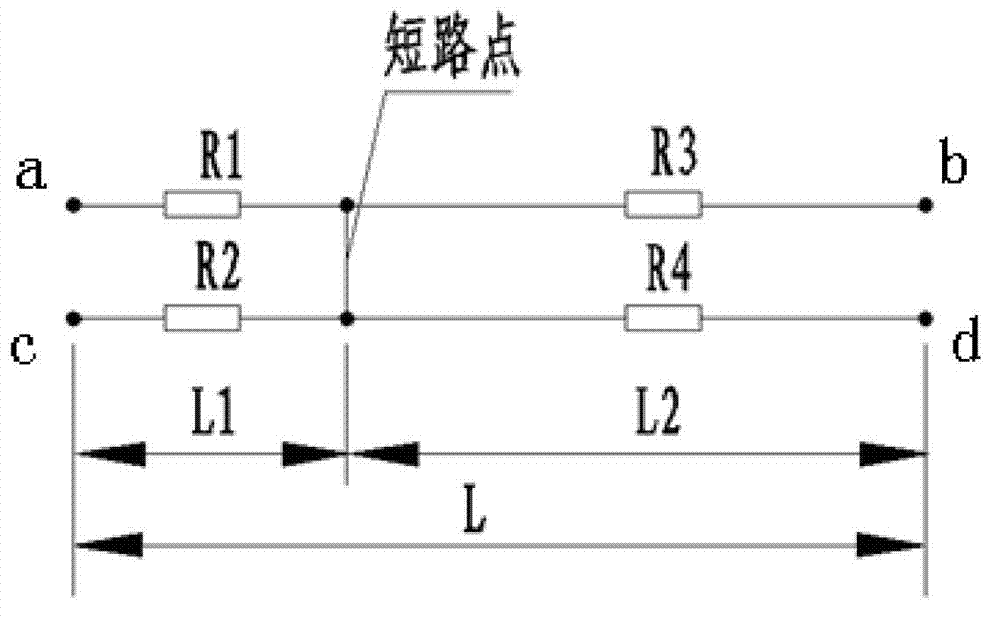
[0017] Such as figure 1 As shown, a cable breakpoint position detection method, assuming that the wire ab and the wire cd are selected as two uniform wires of equal length and equal spacing in the cable,
[0018] The detection steps of cable short-circuit point are as follows:
[0019] a) Connect the two test leads of the resistance testing instrument or equipment to the figure 1 The end point a and end point c shown, the measured wire resistance Rac=R1+R2;
[0020] b) Connect the two test leads of the resistance testing instrument or equipment to the figure 1 The end point a and end point b shown, the measured wire resistance Rab=R1+R3;
[0021] c) Connect the two test leads of the resistance testing instrument or equipment to the figure 1 The end point c and end point d shown, the measured wire resistance Rcd=R2+R4;
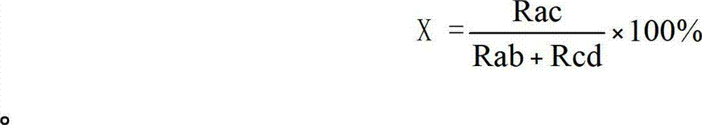
[0022] d) Calculate the relative distance X between the short-circuit point and point c according to formula (1).
[0023] X = ...
PUM
 Abstract
Description
Claims
Application Information