Forward-looking scanning radar imaging method

A scanning radar and imaging method technology, applied in the direction of radio wave reflection/re-radiation, using re-radiation, measuring devices, etc., can solve the problem of poor accuracy of imaging results, slow change of Doppler in the forward-looking area, and increased forward-looking imaging Scene range and other issues

Active Publication Date: 2013-03-13
UNIV OF ELECTRONIC SCI & TECH OF CHINA
View PDF2 Cites 34 Cited by
  • Summary
  • Abstract
  • Description
  • Claims
  • Application Information

AI Technical Summary

Problems solved by technology

In the document "Malenke T., Oelgart T., Rieck W., W-band-radar system in a dual-mode seeker for autonomous target detection, European Conference on Synthetic Aperture Radar, 2002", it is proposed to use Doppler beam sharpening ( DBS, DopplerBeam Shar

Method used


Image

  • Forward-looking scanning radar imaging method
  • Forward-looking scanning radar imaging method
  • Forward-looking scanning radar imaging method

Examples


Embodiment Construction

[0050] The present invention mainly adopts the method of simulation experiment to verify, and all steps and conclusions are verified correctly on Matlab2010. The method of the present invention will be further described below in conjunction with the accompanying drawings and specific embodiments.

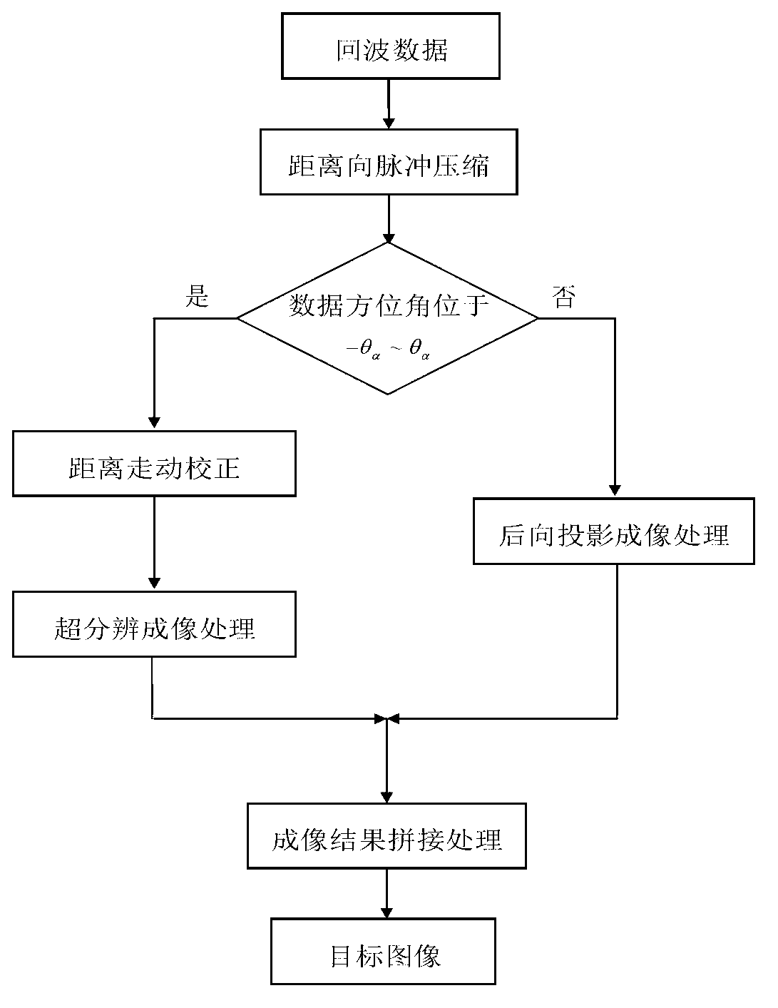
[0051] The schematic flow chart of the forward-looking scanning radar imaging method of the present invention is as figure 1 As shown, the specific process is as follows:

[0052] Step 1: Initialize the parameters of the imaging system.

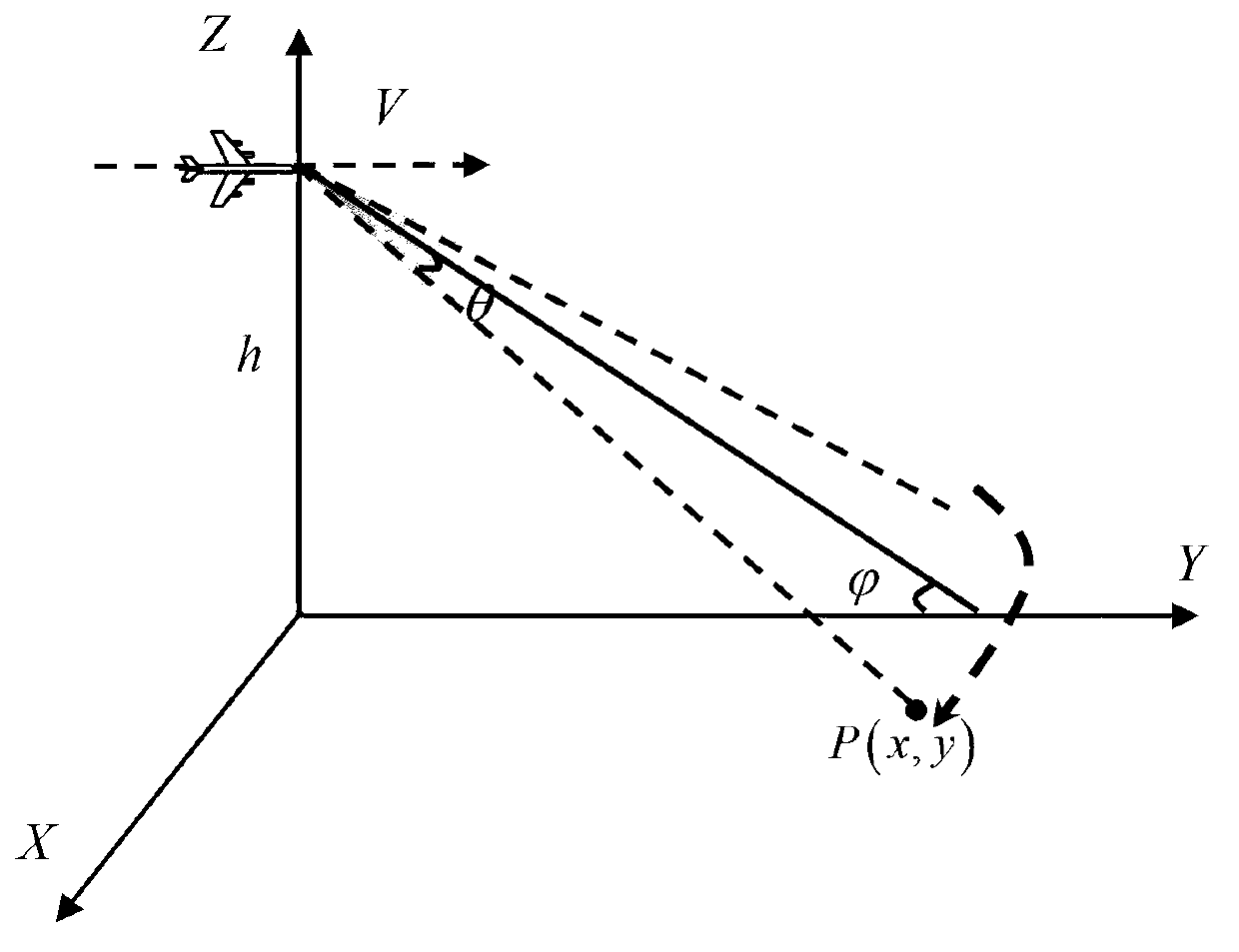
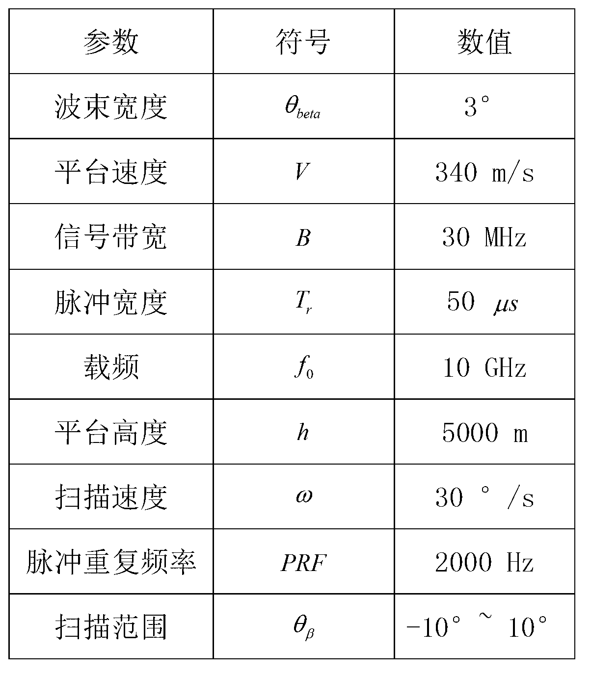
[0053] The imaging geometry mode diagram adopted in this embodiment is as follows figure 2 As shown, the system coordinate system takes the ground point below the radar platform as the coordinate origin, the platform moves along the y-axis, the x-axis is the direction tangential to the track, and the z-axis is the direction vertical to the ground. according to image 3 The data listed initialize the imaging system parameters.

[0054] The tar...


PUM


Abstract

The invention discloses a forward-looking scanning radar imaging method. The method comprise the steps of initializing imaging system parameters; performing range pulse compression on echo data; subjecting a radar right forward-looking area to super-resolution imaging processing; performing back projection imaging processing on a large-azimuth area; and splicing imaging results of the two areas. According to the forward-looking scanning radar imaging method, an ill-posed problem regularization method is utilized, and accordingly, the azimuth resolution is improved, and a back projection algorithm is combined to improve the azimuth resolution of the large-azimuth area. The two imaging results are spliced into a complete scene image, so that the forward-looking scanning radar imaging scene range is expanded, and not only the defect that synthetic aperture radars cannot perform forward-looking imaging is overcome, but also the problem that azimuth imaging scene ranges of prior forward-looking scanning radars are small is solved.

Description

technical field [0001] The invention belongs to the technical field of radar signal processing, and in particular relates to an imaging method in forward-looking scanning radar (Forward-Looking Scanning Radar) technology. Background technique [0002] Microwave imaging technology, as an active aviation and aerospace remote sensing method, has the characteristics of all-weather and all-weather work. It has been widely used in geological surveying and mapping, disaster monitoring, military reconnaissance and other fields. It has become a high-resolution earth observation and global One of the most important means of resource management. However, due to the limitations of its own working system, the existing Synthetic Aperture Radar (SAR) cannot achieve high-resolution imaging in the azimuth direction of the forward-looking area, so that SAR can be used in aircraft forward-looking to the ground, autonomous landing, material airdrops, and missiles. Terminal guidance and other a...

Claims


Application Information

Patent Timeline
IPC IPC(8): G01S13/89
Inventor 刘喆蒋文黄钰林杨建宇李文超武俊杰李中余
Owner UNIV OF ELECTRONIC SCI & TECH OF CHINA
Why Eureka
Try Eureka