Light-emitting diode (LED) constant current driving circuit and LED lamp

A technology of LED driving and constant current driving, applied in the field of circuits, can solve problems such as damage to circuit components, temperature rise of circuit components, fire, etc.

Active Publication Date: 2014-12-10
SHENZHEN SKYWORTH RGB ELECTRONICS CO LTD
View PDF4 Cites 0 Cited by
  • Summary
  • Abstract
  • Description
  • Claims
  • Application Information

AI Technical Summary

Problems solved by technology

[0004] The present invention provides an LED constant current drive overvoltage protection circuit, aiming to solve the problems in the prior art that the Boost booster module or the light bar open circuit or short circuit damages the circuit components or the temperature rise of the circuit components causes a fire.

Method used


Image

  • Light-emitting diode (LED) constant current driving circuit and LED lamp
  • Light-emitting diode (LED) constant current driving circuit and LED lamp
  • Light-emitting diode (LED) constant current driving circuit and LED lamp

Examples


Embodiment 1

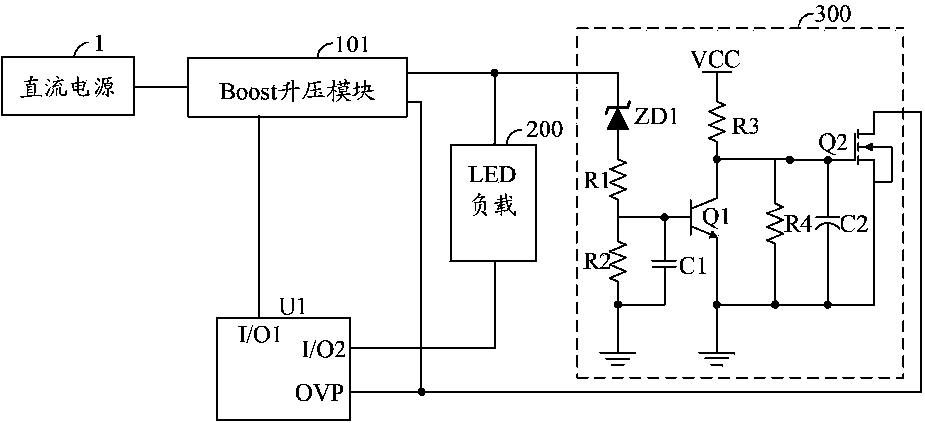
[0027] figure 2 The circuit structure of the LED constant current drive circuit provided by the first embodiment of the present invention is shown. For the convenience of explanation, only the parts related to the first embodiment of the present invention are shown, and the details are as follows:

[0028] As an embodiment of the present invention, the first switching tube 301 adopts an NPN transistor Q1, the base of the NPN transistor Q1 is the control terminal of the first switching tube 301, and the collector of the NPN transistor Q1 is the high potential of the first switching tube 301 terminal, the emitter of the NPN transistor Q1 is the low potential terminal of the first switch tube 301 .

[0029] As an embodiment of the present invention, the second switch tube 302 uses an N-type MOS tube Q2, the gate of the N-type MOS tube Q2 is the control terminal of the second switch tube 302, and the drain of the N-type MOS tube Q2 is the gate of the second switch tube 302. The ...

Embodiment 2

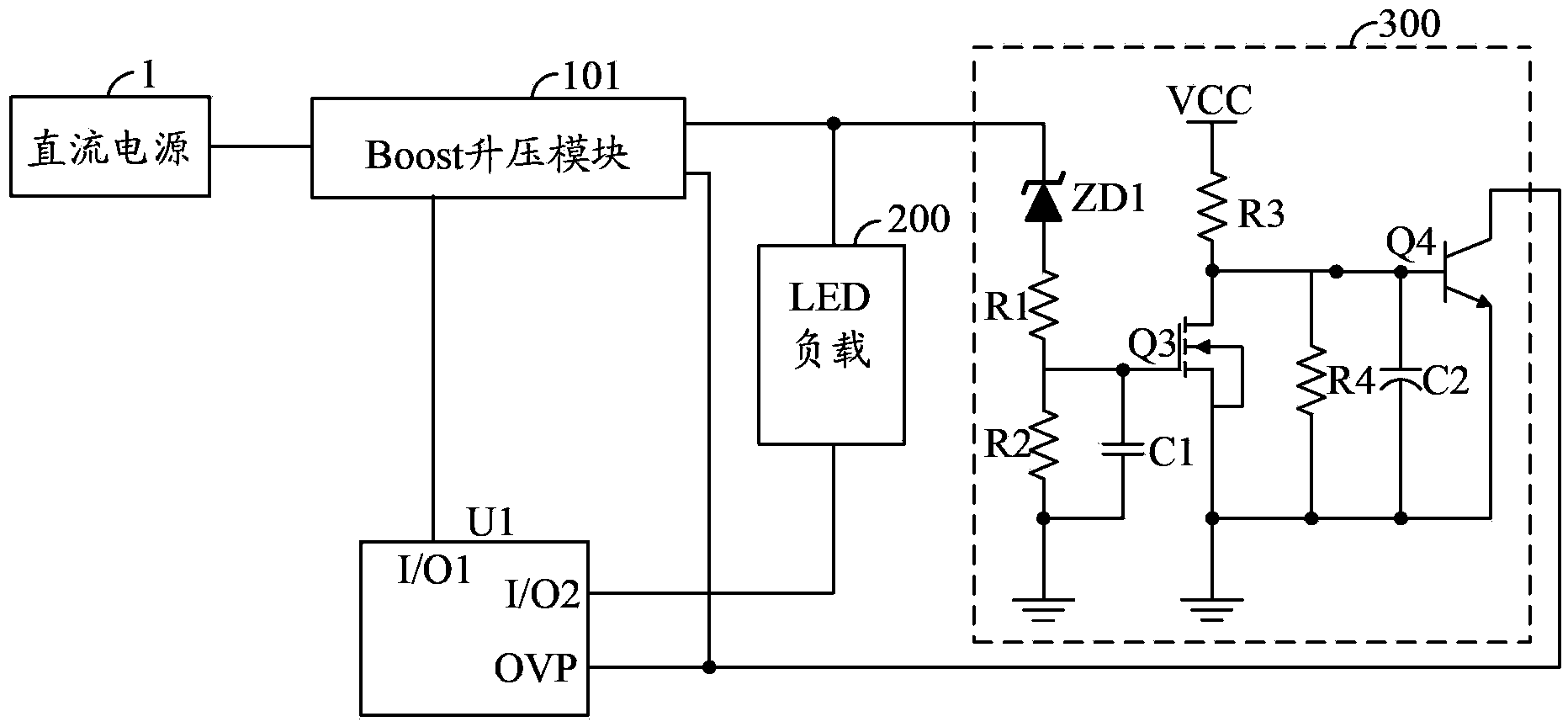
[0033] image 3 The circuit structure of the LED constant current drive circuit provided by the second embodiment of the present invention is shown. For the convenience of explanation, only the parts related to the second embodiment of the present invention are shown, and the details are as follows:

[0034] As an embodiment of the present invention, the first switch tube 301 uses an N-type MOS tube Q3, the gate of the N-type MOS tube Q3 is the control terminal of the first switch tube 301, and the drain of the N-type MOS tube Q3 is the gate of the first switch tube 301. At the high potential end, the source of the N-type MOS transistor Q3 is the low potential end of the first switch transistor 301 .

[0035]As an embodiment of the present invention, the second switch tube 302 uses an NPN transistor Q4, the base of the NPN transistor Q4 is the control terminal of the second switch tube 302, and the collector of the NPN transistor Q4 is the high potential of the second switch t...


PUM


Abstract

The invention belongs to the circuit field and provides a light-emitting diode (LED) constant current driving circuit and an LED lamp. The detection end of an output protection module is connected with the output end of a boost module, the output protection module can timely detect short circuits when the boost module or LED load are shorted out, and an LED driving chip stops working by downwards pulling an overvoltage protection pin connected with the LED driving chip. The problems of circuit element damage caused by boost module or LED load circuit opening or shorting or fire hazards caused by temperature rising of circuit elements are solved.

Description

technical field [0001] The invention belongs to the field of circuits, in particular to an LED constant current drive circuit and an LED lamp. Background technique [0002] LED lights have many advantages such as energy saving, environmental protection, and high efficiency, and are becoming more and more popular at present. It is widely used, and LCD TV based on LED backlight is one of them. [0003] With the development of LED drive technology, there are already many dedicated LED drive chips based on Boost boost modules. This kind of LED driver chip will protect the open circuit and short circuit state of the LED load by setting a special OVP overvoltage protection pin. However, the OVP overvoltage protection pin of the LED driver chip cannot protect the fault state of components such as inductors and diodes in the circuit. When the inductor, diode, etc. in the boost module fail, the temperature of the MOS tube and other components will gradually rise until they are dam...

Claims


Application Information

Patent Timeline
Patent Type & Authority Patents(China)
IPC IPC(8): H05B37/02
Inventor 胡向峰郭继龙鲍晓杰
Owner SHENZHEN SKYWORTH RGB ELECTRONICS CO LTD
Why Eureka
Try Eureka