A piston rod foot

A piston rod and piston technology, applied in the field of injection pens

Inactive Publication Date: 2013-03-13
NOVO NORDISK AS
View PDF10 Cites 8 Cited by
  • Summary
  • Abstract
  • Description
  • Claims
  • Application Information

AI Technical Summary

Problems solved by technology

But none of these known syringes are provided with a piston rod seat

Method used


Image

  • A piston rod foot
  • A piston rod foot
  • A piston rod foot

Examples


Embodiment Construction

[0027] When words such as "upper" and "lower", "right" and "left", "horizontal" and "vertical", "clockwise" and "counterclockwise" or similar relative descriptions are used hereinafter, These refer only to the drawings and not to actual usage. The shown figures are schematic representations, whereby the configuration of the different structures as well as their relative dimensions are intended for descriptive purposes only.

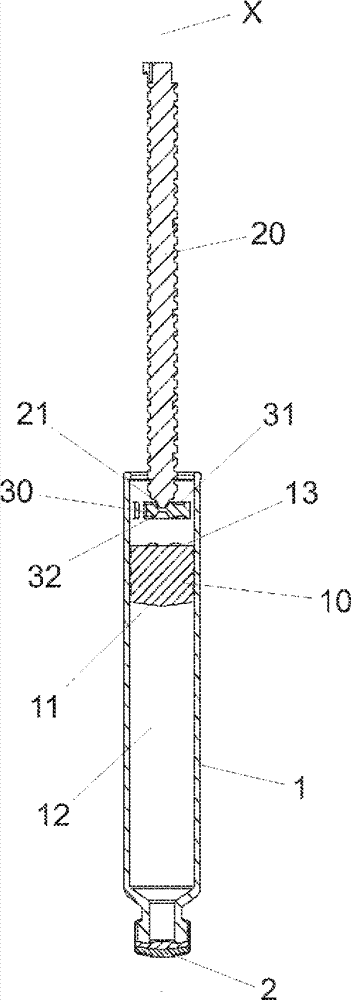
[0028] In this context, it may be convenient to qualify the word "distal" in the figures to mean the end of the needle tube directed towards penetrating the patient, and the word "proximal" to mean the opposite end.

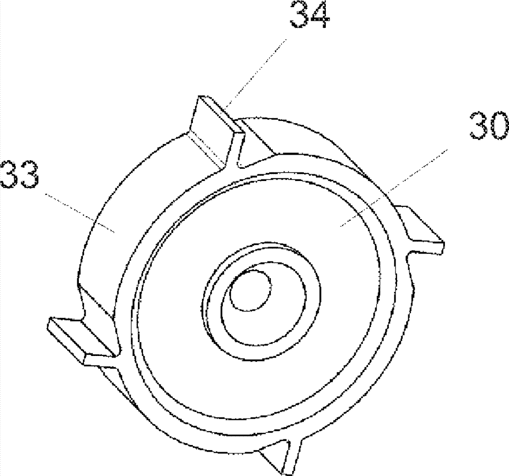
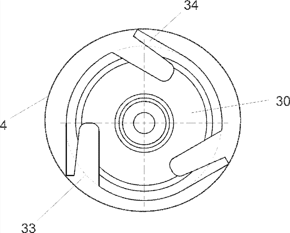
[0029] FIG. 1 discloses a medical drug delivery device, which includes a drug cartridge 1 , a rubber piston 10 , a piston rod 20 and a piston rod seat 30 .

[0030] The cartridge 1 is closed at its distal end by sealing with a flexible membrane 2 which can be pierced by a not shown injection needle. At the proximal end the cartridge 1 is c...


PUM


Abstract

The invention relates to a medical drug delivery apparatus which comprises a cartridge (1) being closed at one end by a flexible membrane (2) and at the opposite end by a movable piston (10). The movable piston rod (19) is moved forward by a piston rod (20). In order to distribute the force from the piston rod (20) to the movable piston (10) a piston rod foot (30) is provided sandwiched between the piston rod (29) and the movable piston (10) The piston rod foot (30) provided between the piston rod (20) and the movable piston (10) has a plurality of arms (34) extending in a direction perpendicular to a longitudinal axis (X) of the cartridge (1) and which arms (34) engages the inner wall (4) of the cartridge (1) thereby obtaining geometric guidance or generating a force of friction between the piston rod foot (30) and the inner wall (4) of the cartridge (1).

Description

technical field [0001] The present invention relates to injection pens in which a piston rod moves a piston or plunger forward within a cartridge, and more particularly the present invention relates to a piston rod seat or a piston rod spacer for such an injection pen. Background technique [0002] People with diabetes are usually able to self-inject insulin on a daily basis. To this end, a large number of different pen systems have been developed during the past 30 years. Common to pen injectors is that they include a container or cartridge for containing the liquid drug to be injected. The cartridge is provided with a piston that moves forward to deliver the liquid drug from the pen to the user. [0003] An example of such a commercially successful injection pen (Flexpen® produced by Novo Nordisk A / S) is given in US6,235,004. The cartridge ( 89 ), as described eg in Figures 15-17, contains the liquid drug to be expelled. At the proximal end the cartridge (89) is closed...

Claims


Application Information

Patent Timeline
Patent Type & Authority Applications(China)
IPC IPC(8): A61M5/315A61M5/28A61M5/24
CPCA61M5/24A61M2005/3151A61M5/31515A61M5/31511A61M5/31513
Inventor H.赫明森
Owner NOVO NORDISK AS
Why Eureka
Try Eureka