Automatic screw locking elastic mechanism

An automatic locking screw and elastic mechanism technology, applied in metal processing, metal processing equipment, manufacturing tools, etc., can solve the problems of unstable operation of the mechanism, material jam, low production efficiency, etc., and achieve the effect of reducing defective products

Active Publication Date: 2013-03-20
上海莘翔自动化科技有限公司
View PDF12 Cites 27 Cited by
  • Summary
  • Abstract
  • Description
  • Claims
  • Application Information

AI Technical Summary

Problems solved by technology

[0002] The existing hardware assembly industry adopts the screw locking method, which is still widely used, but manual screw locking is time-consuming and laborious, and the production efficiency is low; there are also automatic locking screw machines on the market, but the current automatic screw locking machines often fail due to excessive screw pressure. As a result, the sliding teeth will cause scrapping of the locked screw products, and sometimes the locking screw machine will be full of material or jammed in the material channel, causing the entire mechanism to be unstable during operation.

Method used


Image

  • Automatic screw locking elastic mechanism
  • Automatic screw locking elastic mechanism
  • Automatic screw locking elastic mechanism

Examples


Embodiment Construction

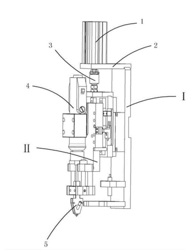
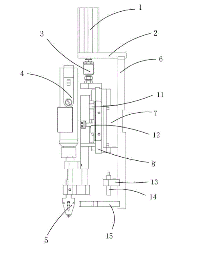
[0018] Examples, see attached Figure 1~4 , an elastic mechanism for automatically locking screws, which includes a push-down cylinder 1, a cylinder mounting plate 2, a floating joint 3, a Z-axis moving mechanism I, a spring mechanism II, an electric bit 4 and a screw chuck 5, and the push-down cylinder is fixedly installed On the cylinder mounting plate, the push-down cylinder is connected with the Z-axis moving mechanism through a floating joint; the spring mechanism is installed on the Z-axis moving mechanism; the electric bit is fixedly installed on the spring mechanism, and the lower end of the electric bit connection screw chuck;

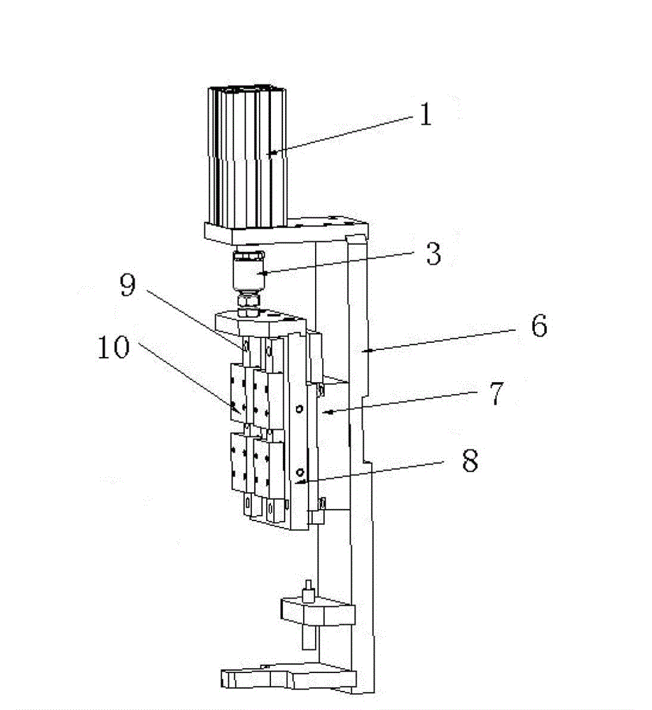
[0019] The Z-axis moving mechanism includes a support plate 6, a guide plate 7, a guide sliding plate 8, a slide rail 9, a slider 10, a Z-axis sensor 11, a Z-axis induction sheet 12, a buffer fixing plate 13, a buffer 14 and Limiting plate 15, the upper end of the support plate is fixedly connected with the cylinder mounting plate, and the lo...


PUM


Abstract

The invention relates to an automatic screw locking elastic mechanism, of which a downward pushing cylinder is connected with a Z-axis moving mechanism; a spring mechanism is arranged on the Z-axis moving mechanism; an electronic screwdriver bit is arranged on the spring mechanism, the lower end of the electric screwdriver bit is connected with a screw chuck; the upper end of a support plate of the Z-axis moving mechanism is connected with a cylinder installation plate, and the lower end of the support plate is connected with a limit plate; a guide plate is arranged on the support plate; a guide sliding plate is arranged on the guide plate, a slide rail is arranged on the guide sliding plate, and a side block is arranged on the slide rail in a matched manner, a moving plate is fixedly connected with the slide block; the upper part of the moving plate is connected with a fixing plate through springs a and b, and the lower part of the moving plate is connected with a buffer plate; a blind hole is arranged in the moving plate, and a spring c is arranged in the blind hole; and a buffer limit pillar penetrates through the buffer plate, is inserted in the blind hole and is in contact with the spring c. Through the driving of the downward pushing cylinder, the electric screwdriver bit is driven to move downwards, meanwhile, a screw is driven to move downwards and to be rotatably attached on a product in a locked manner, the spring mechanism has a protective effect on the screw and the product, and the whole mechanism stably operates.

Description

Technical field: [0001] The present invention relates to an automatic locking screw elastic mechanism, more specifically relates to an automatic locking screw mechanism which completely locks the screw on the product. Background technique: [0002] The existing hardware assembly industry adopts the screw locking method which is still widely used, but manual screw locking is time-consuming and laborious, and the production efficiency is low; there are also automatic locking screw machines on the market, but the current automatic screw locking machines often fail due to excessive screw pressure. As a result, the sliding teeth will cause scrapping of the locked screw products, and sometimes the locking screw machine will be full of material or jammed in the material channel, causing the entire mechanism to be unstable during operation. Invention content: [0003] The purpose of the present invention is to provide an automatic locking screw elastic mechanism. Driven by the cyl...

Claims


Application Information

Patent Timeline
Patent Type & Authority Applications(China)
IPC IPC(8): B23P19/06
Inventor 吕绍林杨愉强吴小平贺鹏
Owner 上海莘翔自动化科技有限公司
Why Eureka
Try Eureka