
Laminating machine having four paper feeding stations

A paper feeding and station technology, applied in pasting, transportation and packaging, decorative arts, etc., can solve the problems of slow paper mounting and increase control difficulty, and achieve the effect of simplifying the structure, improving the mounting speed, and reducing the longitudinal length.

Inactive Publication Date: 2013-03-20
GUANGDONG MAGNOLIA PACKING MACHINERY
View PDF4 Cites 2 Cited by
  • Summary
  • Abstract
  • Description
  • Claims
  • Application Information

AI Technical Summary

Problems solved by technology

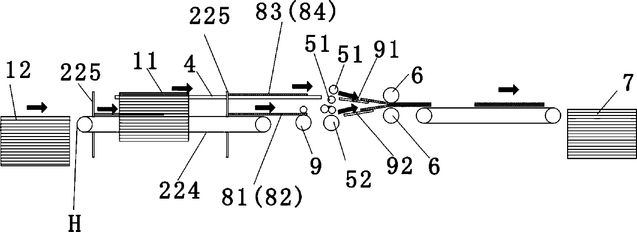
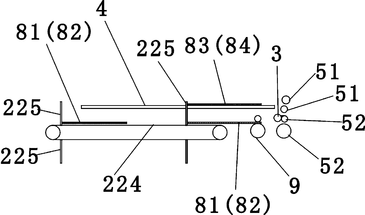
[0005] The existing paper laminating machine has the following disadvantages: first, there are only two paper feeding stations, which are respectively used to convey the upper layer of paper and the lower layer of paper, and the laminating speed is slow; second, from the vertical position, the lower paper feeding mechanism It is flush with the laminating mechanism, while the upper paper-feeding mechanism is higher than the laminating mechanism, such as figure 1 As shown, therefore, the distance between the upper and lower layers of paper is not equal. It is required that the longitudinal positioning gauge 225 of the upper layer of paper feeding mechanism and the longitudinal positioning gauge 225 of the lower layer of paper feeding mechanism must be staggered in the longitudinal direction. The longitudinal positioning gauge 225 of the two layers of paper feeding mechanism Must be set separately, but their longitudinal positions must be precisely matched, which increases the difficulty of control

Method used


Image

  • Laminating machine having four paper feeding stations
  • Laminating machine having four paper feeding stations
  • Laminating machine having four paper feeding stations

Examples


Embodiment Construction

[0027] figure 2 , image 3 , Figure 4 , Figure 5 , Figure 7 As shown, the laminating machine of the four paper feeding stations includes an upper paper feeding station 11, a lower paper feeding station 12, an upper paper feeding mechanism, a lower paper feeding mechanism, an upper rubber roller 3, an upper pinch feeding mechanism, a lower layer Pinching mechanism, laminating mechanism, paper delivery mechanism 7, the pinching mechanism of the upper layer is provided with two pinch rollers 51, and the pinching mechanism of the lower layer is also provided with two nip rollers 52, and the laminating mechanism is provided with two pressure rollers 6; The paper feeding station 12 is located behind the lower paper feeding mechanism, the lower paper feeding mechanism is located behind the lower pinch mechanism, the upper rubber roller 3 is close to the lower pinch mechanism, the upper paper feeding mechanism is located behind the upper pinch mechanism, and the upper pinch Th...


PUM


Abstract

The invention provides a laminating machine having four paper feeding stations. A lower-layer paper feeding station is placed behind a lower-layer paper feeding mechanism which is placed behind a lower-layer pinch mechanism, an upper rubber covered roller is close to the lower-layer pinch mechanism, and an upper layer paper feeding mechanism is placed behind an upper-layer pinch mechanism, and the upper-layer pinch mechanism and the lower-layer pinch mechanism are placed behind the laminating machine. The upper-layer paper feeding mechanism is provided with three upper-layer paper guide ribs, the middle upper-layer paper guide rib is a straight line section which is stretched longitudinally, the rear end sections of the upper-layer paper guide ribs on the left side and the right side are in splayed shape, a group of long strip supporting plates are arranged between each two adjacent upper-layer paper guide ribs, a transverse gap is formed between each two adjacent long strip supporting plates in the same group, a longitudinal setting gauge of the lower-layer paper feeding mechanism upwards penetrates through the transverse gaps, the upper-layer paper feeding stations are two in number, and the paper feeding directions of the upper-layer paper feeding stations are transversely inward. The laminating machine can improve pasting speed, accurate match of longitudinal positions of upper-layer paper and lower-layer paper can be easily controlled, and components are saved.

Description

[0001] technical field [0002] The invention belongs to the technical field of paper laminating machines, and in particular relates to a paper laminating machine with four paper feeding stations. Background technique [0003] The laminating machine is used to laminate two or more sheets of paper together by pasting. Such as figure 1 As shown, the laminating machine includes an upper paper feeding station 11, a lower paper feeding station 12, an upper paper feeding mechanism, a lower paper feeding mechanism, an upper rubber roller, an upper pinching mechanism 51, a lower pinching mechanism 52, and a laminating mechanism. , Paper receiving mechanism 7. Wherein the upper layer paper feeding station 11 is responsible for outputting the upper layer paper 83, the lower layer paper feeding station 12 is responsible for outputting the lower layer paper 81, and the upper layer paper feeding mechanism is responsible for horizontally pushing the upper layer paper 83 output by the up...

Claims


Application Information

Patent Timeline
IPC IPC(8): B44C7/02B65H29/16
Inventor 李钟荣李飚康忠凯
Owner GUANGDONG MAGNOLIA PACKING MACHINERY
Learn More