
Ventilating fan orifice door

A ventilation fan and orifice technology, which is applied in the direction of windows/doors, wing parts, door/window accessories, etc., can solve the problems of vent closure, ventilation equipment damage, and unreasonable problems, so as to prevent air pollution, reduce noise, Practical and reliable effect

Active Publication Date: 2013-03-20
SUZHOU JIANGNAN AEROSPACE MECHANICAL& ELECTRICAL IND CO LTD
View PDF7 Cites 12 Cited by
  • Summary
  • Abstract
  • Description
  • Claims
  • Application Information

AI Technical Summary

Problems solved by technology

If the wall is deformed or squeezed for a long time, it will cause damage to the ventilation equipment.
Moreover, this type of ventilation equipment cannot close the vents, because the vents are permanently open, which is not very reasonable.

Method used


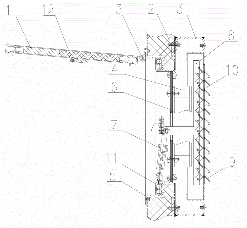
Image

  • Ventilating fan orifice door
  • Ventilating fan orifice door
  • Ventilating fan orifice door

Examples


Embodiment Construction

[0016] The preferred embodiments of the present invention will be described in detail below in conjunction with the accompanying drawings, so that the advantages and features of the present invention can be more easily understood by those skilled in the art, so as to define the protection scope of the present invention more clearly.

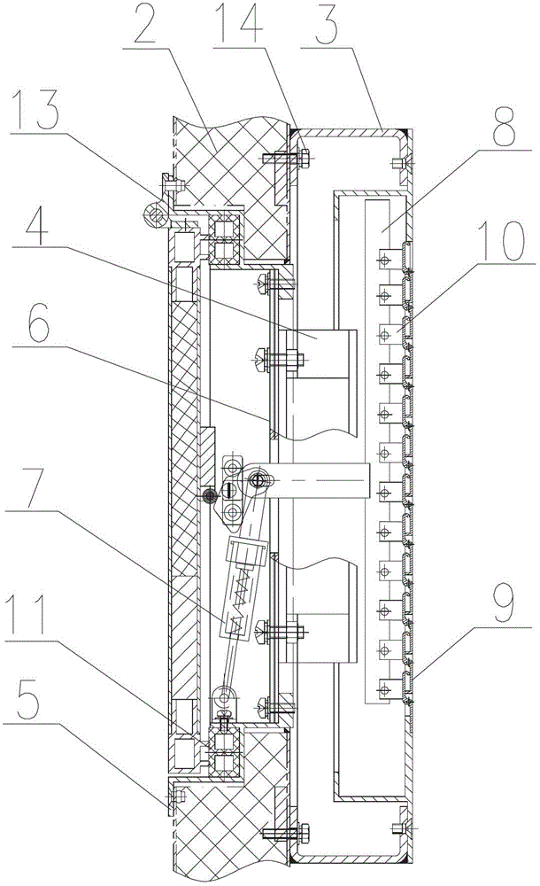
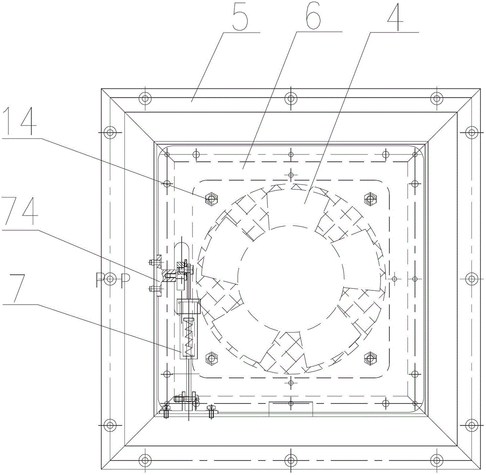
[0017] Please refer to the attached figure 1 and 5 , the embodiment of the present invention includes:

[0018] A ventilation fan opening door, which includes: a door panel 1, an outer door frame 2, an inner door frame 3 and an axial flow fan 4; Solid; the door panel 1 is connected to the front of the outer door frame 2 through a hinge 13; a touch head 12 is installed on the side of the door panel 1; a circle of metal edge strips 5 is riveted on the inner side of the outer door frame 2; A rectangular dust-proof screen 6 is sealed at the passageway matched with the inner door frame 3; the center of the dust-proof screen 6 is a circular filter; t...


PUM


Abstract

The invention relates to a ventilating fan orifice door, which comprises a door plate, an outer door frame, an inner door frame and an axial-flow fan. The door plate is hinged with the front surface of the outer door frame. A turn of metal edging strip is riveted on the internal side of the outer door frame. A rectangular dustproof screen plate is sealed at the full diameter of the boundary of the outer door frame and the inner door frame. The dustproof screen plate is connected with the axial-flow fan in the inner door frame through bolts and nuts. An automatic louver opening mechanism is fixedly arranged on the internal side of the outer door frame. The automatic louver opening mechanism can penetrate through a through hole at a corresponding position on the edge of the dustproof screen plate and is connected to a deflector rod on the side of the inner door frame. A louver at the air outlet of the inner door frame is fixedly connected onto the deflector rod. A touch head is installed on the side of the door plate. By adopting the technical scheme, the axial-flow fan is built in the ventilating fan orifice door and the automatic louver opening mechanism is used for opening and closing the louver. When the door plate is opened, the touch head loses pressure, a spring mechanism contracts and a connecting rod pulls the deflector rod to move downwards to open the louver; and reversely, the louver is closed.

Description

technical field [0001] The invention relates to a building ventilation structure, in particular to a ventilation fan opening door. Background technique [0002] In the field of construction, the ventilation structure is used for the exchange of indoor and outdoor air, which plays the role of air circulation and changing room temperature. Ventilation equipment is widely used in daily life and industrial production because of its good working performance. But how to place these devices reasonably is a practical problem. In many buildings, holes are cut in the walls and ventilation equipment is positioned so that the wall presses directly on the equipment. If the wall is deformed or squeezed for a long time, it will cause damage to the ventilation equipment. And this type of ventilator can't close the vent, because the vent is permanently open, which is not very reasonable. Contents of the invention [0003] The technical problem mainly solved by the present invention is...

Claims


Application Information

Patent Timeline
Patent Type & Authority Applications(China)
IPC IPC(8): E06B7/084E06B7/02E05F1/08E05F7/04
Inventor 苏云涛施强光王海军
Owner SUZHOU JIANGNAN AEROSPACE MECHANICAL& ELECTRICAL IND CO LTD
Learn More