Reversing valve of hydraulic piston pump

A technology of hydraulic piston and reversing valve, which is applied to pump components, variable displacement pump components, and components of pumping devices for elastic fluids, etc., can solve the problem of low efficiency and low pumping efficiency of beam pumping units. and other problems, to achieve the effect of simple processing, improving processing accuracy and reducing manufacturing difficulty

Inactive Publication Date: 2013-03-20
张金生
View PDF6 Cites 7 Cited by
  • Summary
  • Abstract
  • Description
  • Claims
  • Application Information

AI Technical Summary

Problems solved by technology

At present, the commonly used oil production equipment is still the conventional beam pumping unit with low oil pumping efficiency. Although various measures have been taken, the problem of low effi

Method used


Image

  • Reversing valve of hydraulic piston pump
  • Reversing valve of hydraulic piston pump

Examples


Embodiment Construction

[0028] The present invention is described below in conjunction with the accompanying drawings.

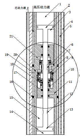
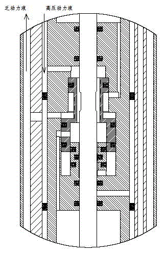
[0029] attached figure 1 It is a schematic diagram of the reversing valve structure of a commonly used hydraulic piston pump. The E-type hydraulic piston pump of the American KEBO company adopts this structure. The only domestic manufacturer of hydraulic piston pumps is the hydraulic piston pump produced by Shengli Oilfield Rodless Pump Co., Ltd. Reversing valves are of this type. In the prior art, the mutually moving parts in its structure are separated by gaps. The structure of the present invention is different from the prior art in that, figure 1 In the structure shown, there are step seals or lattice circles, that is, the parts represented by small black squares, between the parts that move with each other.

[0030] The working principle of the present invention is: when the reversing valve 8 is at the upper limit position, the high-pressure power fluid enters the upper end...


PUM


Abstract

The invention discloses a method for carrying out dynamic sealing between kinematic pairs in a reversing valve of a hydraulic piston pump and the reversing valve, which is subjected to sealing by adopting the method, of the hydraulic piston pump. The method and the reversing valve of the hydraulic piston pump have the technical characteristics that all movable fitting pieces of the reversing valve of the hydraulic piston pump are subjected to sealing by adopting Glyd rings or Step-seal-combined sealing members. The method and the reversing valve of the hydraulic piston pump have the advantages that the problem of dynamic sealing of the hydraulic piston pump when water is used as a power medium is solved, and power media used by the hydraulic piston pump can be diversified; the operation of the reversing valve can be stable, and the dynamic sealing effect is more reliable; the advantages of the hydraulic piston pump are fully played, so that the hydraulic piston pump can be more widely applied to oilfields and replace a walking-beam oil pumping machine; and the service lives of the sealing members of the reversing valve can be greatly prolonged.

Description

technical field [0001] The invention relates to a method for dynamic sealing between kinematic pairs of a hydraulic element used in oil pumping operations in an oil field, and the hydraulic element sealed by the method. To be precise, the present invention dynamically seals the kinematic pair of the reversing valve of the hydraulic piston pump, and is especially applied to the reversing valve that uses water as the power fluid for oil pumping operations in oil fields and performs reversing movement under high pressure conditions. A method for dynamic sealing between moving pairs of elements, and a hydraulic piston pump reversing valve for dynamic sealing between moving parts using the method of the invention. Background technique [0002] The hydraulic piston pump system is a hydraulically driven rodless pumping equipment, which is a kind of equipment used to pump oil from deep underground holes. It is powered by a ground power pump to pressurize the power fluid and pump it...

Claims


Application Information

Patent Timeline
IPC IPC(8): F04B53/12
Inventor 张金生
Owner 张金生
Why Eureka
Try Eureka