Method for filling catalyst in tube type reactor

A tube-and-tube reactor and catalyst technology, applied in chemical instruments and methods, chemical/physical processes, etc., can solve problems such as uneven filling of catalysts, and achieve the effects of good filling effect, easy operation and uniform filling.

Active Publication Date: 2015-05-20
CHINA PETROLEUM & CHEM CORP +1
View PDF4 Cites 0 Cited by
  • Summary
  • Abstract
  • Description
  • Claims
  • Application Information

AI Technical Summary

Problems solved by technology

[0007] The purpose of the present invention is to provide a catalyst loading method for a tubular fixed-bed reactor to solve the problem of uneven catalyst loading in the prior art

Method used


Image

  • Method for filling catalyst in tube type reactor
  • Method for filling catalyst in tube type reactor

Examples


Embodiment 1

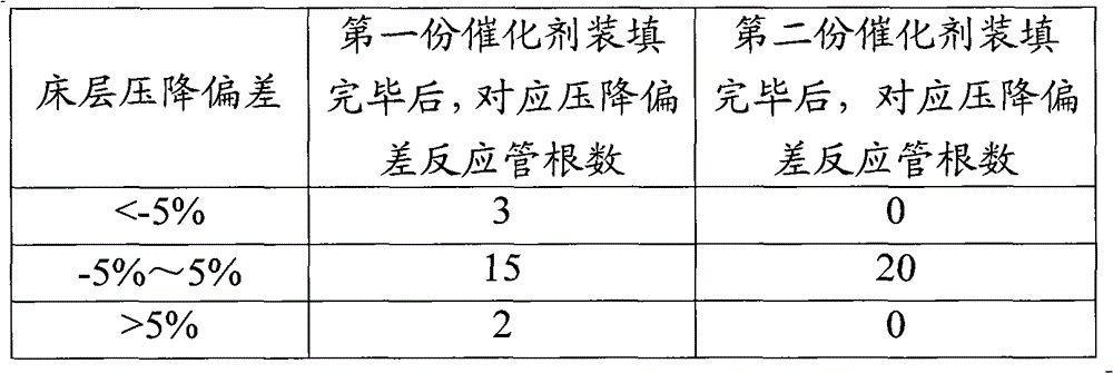
[0031] Take 20 aforementioned glass tubes and place them vertically, install a plugging spring at the bottom of each glass tube, and fill the upper part of the plugging spring with 100 mm high Φ3 mm ceramic balls to avoid catalyst leakage during the filling process. According to calculation, the amount of catalyst loaded theoretically in each glass tube is 4kg, and according to the method of the present invention, 20 parts of 2kg catalysts are prepared in total. Load the first part of catalyst evenly into each glass tube, and control the rising speed of the catalyst bed height to 25mm / s (v1). See Table 1 for deviation statistics.

[0032] It can be seen that there are two glass tubes with a pressure drop higher than 5% of the average pressure drop; three glass tubes with a pressure drop lower than 5% of the average pressure drop. Carry out the loading of the second part of catalyst according to the method of the present invention: the glass tube with pressure drop lower than ...


PUM


Abstract

The invention discloses a method for filling a catalyst in a tube type reactor. The method comprises the following steps of: (1) halving the catalyst to be filled in each reaction tube; (2) filling the first part of the catalyst in each reaction tube and controlling the rising velocity of the height of each catalyst bed layer as v1; (3) measuring pressure drop of each reaction tube; and (4) filling the second part of the catalyst in each reaction tube. The method for filling the catalyst in the tube type reactor, disclosed by the invention, improves uniformity of the catalyst filled in each reaction tube and lowers filling difficulty of the catalyst.

Description

technical field [0001] The invention relates to a catalyst loading method for a tubular reactor. Background technique [0002] For a strongly exothermic reaction system, a tubular fixed-bed reactor is a preferred reactor form. The catalyst loading of the tubular fixed-bed reactor is the key factor affecting the success of the plant. Uneven catalyst loading will cause the raw material flow in the reaction stage, which will cause the reaction effect to deteriorate, and cause the catalyst bed to overheat and stop the operation. In order to make the catalyst loading more uniform, there are the following catalyst loading techniques. [0003] CN1607032A discloses a method for loading catalyst. In the method, during the catalyst filling process, a chain substance is inserted into the reaction tube so that the lower end of the chain substance is higher than the upper end of the catalyst layer. This method can largely avoid the occurrence of "bridging" phenomenon during the cataly...

Claims


Application Information

Patent Timeline
Patent Type & Authority Patents(China)
IPC IPC(8): B01J8/06
Inventor 吴昊胡志海聂红徐润李猛侯朝鹏孙霞
Owner CHINA PETROLEUM & CHEM CORP
Why Eureka
Try Eureka