Punch press

A punching machine and base technology, applied in the field of punching machines, can solve the problems of being unsuitable for stamping and forging of small parts, large energy consumption of small parts, and bulky punching machine, so as to achieve less use of materials and energy, protection of resources, and small size. Effect

Inactive Publication Date: 2013-03-27
苏州天盛电线电缆有限公司
View PDF7 Cites 21 Cited by
  • Summary
  • Abstract
  • Description
  • Claims
  • Application Information

AI Technical Summary

Problems solved by technology

[0002] The punching press is a stamping press, and the stamping process saves materials and energy and has high efficiency compared with general mechanical processing. The stamping process is widely used in mechanical processing, but the existing punch...

Method used


Image

  • Punch press

Examples


Embodiment Construction

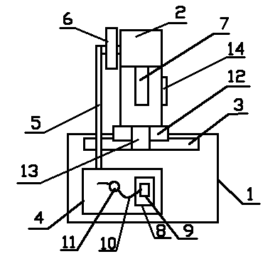
[0010] In this example, refer to figure 1 As shown, a stamping machine of the present invention includes a machine base 1, a column 2 arranged on the machine base 1, and a working platform 3 arranged on the machine base 1, and a hydraulic power device is arranged in the machine base 1 4. The hydraulic power unit 4 is externally connected with a hinge connection mechanism 5, and a flywheel mechanism 6 is provided on the top of the pole 2, and one end of the hinge connection mechanism 6 is connected to the flywheel mechanism 6 on the pole 2, and the flywheel A stamping device 7 is connected to the lower end of the mechanism 6 .

[0011] The hydraulic power unit 4 includes a fuel tank 8, a hydraulic cylinder 9, an oil pipe 10 and a flow valve 11, the hydraulic cylinder 9 is arranged in the fuel tank 8, the oil pipe 10 is connected to the hydraulic cylinder 9, and through the oil pipe 10 and the hydraulic cylinder 9 The oil is transported to the flywheel mechanism 6 to generate p...


PUM


Abstract

The invention discloses a punch press which comprises a base, a stand column and a working platform, wherein the stand column is arranged on the base, the working platform is arranged on the base, a hydraulic power device is arranged in the base, the hydraulic power device is externally connected with an articulated juncture mechanism, the top of the stand column is provided with a flywheel mechanism, one end of the articulated juncture mechanism is connected to the flywheel mechanism on the stand column, and the lower end of the flywheel mechanism is connected with a punching device; oil is transported to the flywheel mechanism through an oil pipe and a hydraulic cylinder so as to make power; and the adjustment on oil amount can be realized through a flow valve, and in the process of punching, a lighting device can achieve a lighting effect on the working platform, thereby ensuring the safety in the process of punching operation.

Description

technical field [0001] The invention relates to mechanical processing, in particular to a stamping machine. Background technique [0002] The punching press is a stamping press, and the stamping process saves materials and energy and has high efficiency compared with general mechanical processing. The stamping process is widely used in mechanical processing, but the existing punching machines are bulky and can only process some large stamping parts, which is not suitable for Some small parts are stamped and forged, and the energy consumption is large when processing small parts, the sensitivity is low, and the operation is inconvenient. Contents of the invention [0003] The technical problem to be solved by the present invention is to provide a stamping machine with sensitive operation, small consumables and convenient operation. [0004] In order to solve the above technical problems, the present invention adopts the following technical solutions to achieve: a stamping ...

Claims


Application Information

Patent Timeline
IPC IPC(8): B30B1/16B30B15/00
Inventor 许斌
Owner 苏州天盛电线电缆有限公司
Why Eureka
Try Eureka