Walking mechanism for middle/low-speed maglev vehicles

A traveling mechanism and magnetic levitation technology, applied in railway car body parts, bogies, transportation and packaging, etc., can solve problems such as the lack of effective suppression of over-nodding motion, the lack of anti-detachment device for the sliding table mechanism, and the reduction of the vehicle floor height. , to achieve the effect of convenient daily maintenance, space reduction and weight reduction

Active Publication Date: 2013-03-27
常州西南交通大学轨道交通研究院 +1
View PDF6 Cites 29 Cited by
  • Summary
  • Abstract
  • Description
  • Claims
  • Application Information

AI Technical Summary

Problems solved by technology

[0004] The running mechanism of the existing medium and low-speed maglev vehicles has the following deficiencies: 1. There are many parts installed on the suspension frame, the structure is complex, the manufacturing cost is high, and it is not convenient for daily maintenance
2. The existence of bolsters and Z-shaped drawbars is not conducive to lowering the height of the vehicle floor, requiring a large installation space
3. There is no anti-disengagement device in the sliding table mechanism, and there are certain safety hazards when the curve passes
4. The connecting device between the suspension frames lacks effective restraint on the excessive nodding motion of the suspension frames

Method used


Image

  • Walking mechanism for middle/low-speed maglev vehicles
  • Walking mechanism for middle/low-speed maglev vehicles
  • Walking mechanism for middle/low-speed maglev vehicles

Examples


Embodiment Construction

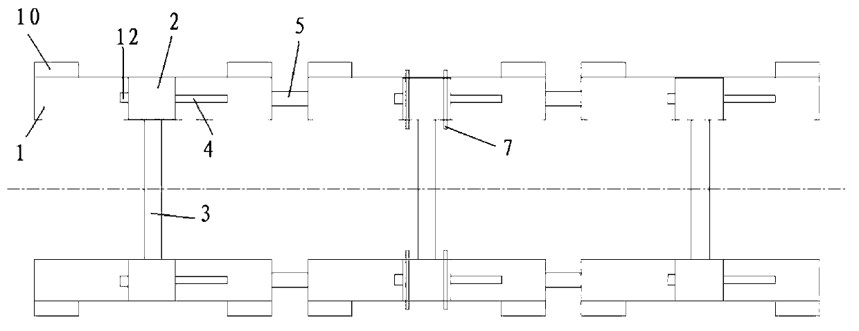
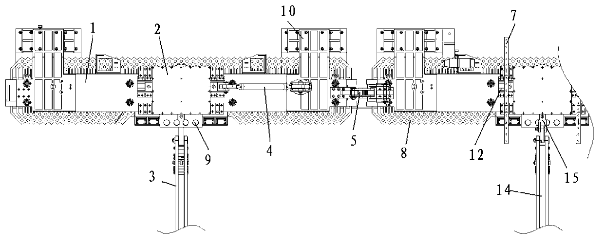
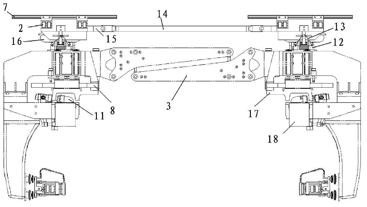
[0023] Such as figure 1 , 2 As shown in and 3, a running mechanism of a medium-low speed maglev vehicle includes at least two end suspension frames and at least one intermediate suspension frame, the end suspension frames are arranged on the front and rear sides of the middle suspension frame, and the end suspension frames and the middle suspension frame Suspension frame all comprises two longitudinal beams 1, slide table 2, air spring 16, transverse tie rod 14 and anti-rolling tie bar 3 that are arranged on the left and right, slide table 2 and air spring 16 all are positioned at the middle position of longitudinal beam 1, each longitudinal beam A sliding table 2 is set on the beam 1, and the sliding table 2 is fixedly supported on the longitudinal beam 1 by an air spring 16. The sliding tables 2 are connected by transverse tie rods 14, and the ends of the transverse tie rods 14 pass through the tie rods arranged inside the sliding table 2. The seat 15 is hinged with the sli...


PUM


Abstract

The invention relates to the technical field of walking mechanisms for maglev vehicles, and particularly relates to a walking mechanism for middle / low-speed maglev vehicles. The walking mechanism for middle / low-speed maglev vehicles comprises at least two end part suspension frames and at least an intermediate suspension frame, each suspension frame comprises two longitudinal beams, sliding tables, air springs, a transverse draw bar and an anti-side-rolling draw bar, wherein the two longitudinal beams are arranged in a left and right mode, the sliding tables and the air springs are arranged in the middle of the longitudinal beams, each longitudinal beam is provided with a sliding table, the sliding table is fixedly supported on the longitudinal beam through the air spring, the sliding tables are connected through the transverse draw bar, the longitudinal beams are connected through the anti-side-rolling draw bar, the transverse draw bar and the anti-side-rolling draw bar are located in the middle of the suspension frame, the sliding tables of the intermediate suspension frame are provided with a linear guide rail extending along the transverse direction, the sliding tables of the intermediate suspension frame are connected with a train body through the linear guide rail, and the sliding tables and the longitudinal beams are connected through traction bars. The walking mechanism disclosed by the invention has the beneficial effects that as a method that the sliding tables are arranged in the middle of the suspension frames and a linear bearing replaces a swing bolster and a Z-shaped traction bar is adopted, the structure of the walking mechanism is simplified, and the walking mechanism is convenient to maintain.

Description

technical field [0001] The invention relates to the technical field of a running mechanism of a magnetic levitation vehicle, in particular to a running mechanism of a medium-low speed magnetic levitation vehicle. Background technique [0002] Medium and low-speed maglev trains are a new type of transportation for urban passenger rail transit. They have the advantages of low noise, strong acceleration and braking capabilities, strong climbing capabilities, small turning radius, low vibration, and good comfort. Usually, the carriages of medium and low-speed maglev trains use the same running mechanism. In order to ensure that the maglev vehicle can pass through the curved track smoothly and stably, the two ends of the carriage are connected with two fixed-point suspension frames, and the middle is connected with several mobile suspension frames. [0003] The traditional fixed-point and mobile suspension frames have air springs and sliding tables at the four ends of the two lo...

Claims


Application Information

Patent Timeline
Patent Type & Authority Applications(China)
IPC IPC(8): B61F5/00
Inventor 马卫华臧宇罗世辉
Owner 常州西南交通大学轨道交通研究院
Why Eureka
Try Eureka