Molten glass cluster shunting mechanism

A shunt mechanism and a technology for melting glass, applied in glass manufacturing equipment, manufacturing tools, etc., can solve the problems of glass mass hitting the edge of the shunt tank, poor working stability of the cylinder, and insufficient advance of the shunt tank, etc., to achieve simple structure and stable operation. , the effect of high work efficiency

Active Publication Date: 2014-12-10
张晓亮
View PDF5 Cites 0 Cited by
  • Summary
  • Abstract
  • Description
  • Claims
  • Application Information

AI Technical Summary

Problems solved by technology

In the existing equipment, the shunt slot is fixed at the front end of the cylinder, and the position of the shunt slot is realized by moving forward or backward of the cylinder. Due to the unstable air source, the working stability of the cylinder is poor, and the shunt slot does not move forward or reset completely, making the The glass ball hits the edge of the splitter tank or falls outside the splitter tank, which cannot complete the material distribution work well, and needs to be shut down for maintenance, which affects the normal operation of the equipment and low production efficiency

Method used


Image

  • Molten glass cluster shunting mechanism
  • Molten glass cluster shunting mechanism
  • Molten glass cluster shunting mechanism

Examples


Embodiment Construction

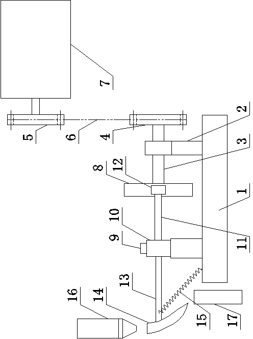
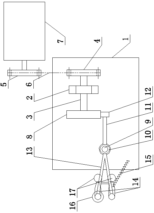
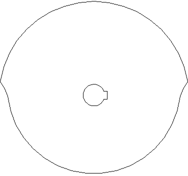
[0014] Such as figure 1 , figure 2 and image 3 The shown molten glass mass diversion mechanism includes a splitter base 1 and a vertical splitter shaft 9 on the splitter base 1, a bearing seat and a bearing 2, and a horizontally arranged transmission is installed on the bearing inner ring of the bearing seat and the bearing 2. Axis 3. One end of the transmission shaft 3 near the vertical distribution shaft 9 is provided with a diverter cam 8, and the other end of the transmission shaft 3 is connected with the driving mechanism. The driving mechanism includes a motor 7, a driving sprocket 5 and a driven sprocket 4, and the driving sprocket 5 Installed on the output end of the motor 7, the driven sprocket 4 is installed on the transmission shaft 3, and the driving sprocket 5 and the driven sprocket 4 are connected through a chain 6 transmission. A sleeve 10 is sleeved on the vertical diverter shaft 9, and a toggle rod 11 and a diverter frame 13 are arranged on the outside o...


PUM


Abstract

The invention relates to a molten glass cluster shunting mechanism. The molten glass cluster shunting mechanism comprises a shunting machine base, a vertical shunting shaft, a bearing seat and a bearing, wherein the bearing seat and the bearing are internally provided with transmission shafts; one end of each transmission shaft is provided with a shunting cam, and the other end of the transmission shaft is connected with a driving mechanism; the vertical shunting shaft is rotationally sleeved with a sleeve pipe; the outer side of the sleeve pipe is respectively provided with a shifting rod and a shunting rack, the end part of the shifting rod is in contact with the outer edge of the shunting cam, and the end part of the shunting rack is provided with shunting grooves; and the sleeve pipe is provided with a reset mechanism. According to the invention, stable operation is achieved; when a reset tension spring is in a contraction state, one of the shunting grooves is communicated with a flow guide part and a material receiving pipe paired with the shunting groove; the shunting cams rotate to push the shifting rod to rotate, and the shunting rack on the sleeve pipe rotates with the shifting rod and stretches the reset tension spring so that the other shunting groove moves below the flow guide part, therefore the communication of the flow guide part and the material receiving pipe paired with the shunting groove is ensured; and the two shunting grooves are circularly changed in position under the action of the rotation of the shunting cams and the acting force of the reset tension spring, therefore the shunting of glass clusters is realized.

Description

technical field [0001] The invention belongs to the technical field of glass bottle forming equipment, and in particular relates to a molten glass mass diversion mechanism. Background technique [0002] In the production process of glass bottles, the molten glass flowing out from the feeder is introduced into a thermoforming device. Between the feeder and the thermoforming device, there are glass lump scissors, flow guides and paired splitters and Feeding tube. The glass ball scissors cut the glass moisture in the molten state to form a glass ball, and the glass ball falls through the flow guide, and by changing the position of the flow guide, the different flow slots correspond to the flow guide, and the flow corresponding to the flow guide The groove guides the glass ball into the corresponding material receiving pipe to realize the material distribution of the glass ball. In the existing equipment, the shunt slot is fixed at the front end of the cylinder, and the positi...

Claims


Application Information

Patent Timeline
Patent Type & Authority Patents(China)
IPC IPC(8): C03B7/22
Inventor 张晓亮张志远
Owner 张晓亮
Why Eureka
Try Eureka