


Quick Research
Generate reliable direction feasibility study reports for your R&D in just a few steps.

Technical Q&A
Discover and master advanced knowledge NOW. Basics, ideas, possibilities, all at once.

Find Solutions
As an expert in R&D theories, this can generate solutions to your technical problems instantly.

Evaluate Feasibility
Analyze your overall solution with one click, know your potential R&D risks in advance.

Monitor Landscape
Get weekly tech updates, stay abreast of the latest tech innovations and key insights.
Electromagnetic actuator
An electromagnetic actuator and magnetic force technology, applied in the direction of electromagnets, electromagnets with armatures, magnets, etc., can solve problems such as the reduction of magnetic attraction force
- Summary
- Abstract
- Description
- Claims
- Application Information
AI Technical Summary
Problems solved by technology
Method used
Image

Examples
no. 1 example
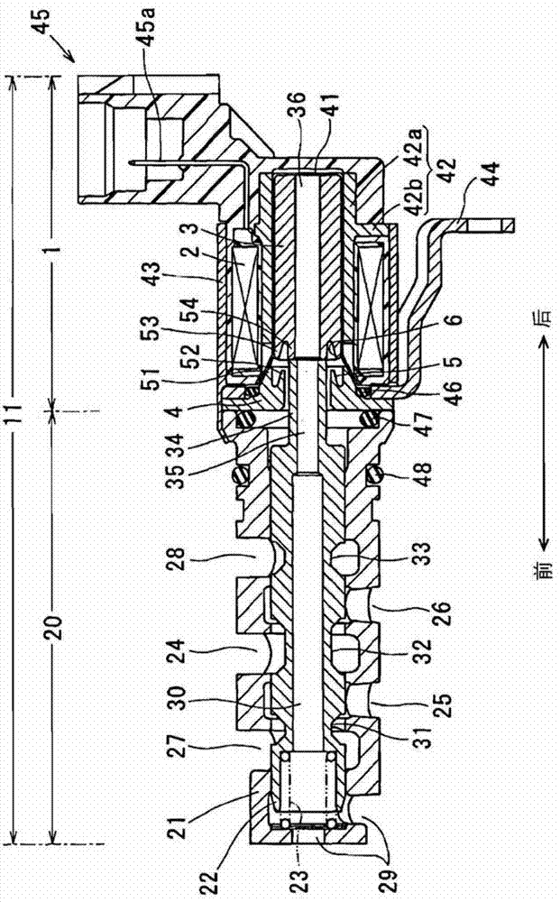
[0028] refer to Figure 1-3 , the first embodiment will be described hereinafter. A VVT controller mounted to the engine has a VCT mechanism 10 that is connected to an intake / exhaust camshaft and continuously changes the rotational phase of the camshaft relative to the crankshaft, thereby continuously adjusting the valve timing of the intake / exhaust valves.
[0029] Further, the VVT controller has a hydraulic circuit 12 including an oil control valve (OCV) 11 hydraulically controlling the VCT mechanism 10 a and an electronic control unit (ECU) 13 electrically controlling the OCV 11 .
[0030] The VCT mechanism 10 has a shoe 14 that rotates in synchronization with the crankshaft of the engine, and a vane rotor 15 that rotates with the camshaft relative to the shoe 14 . A hydraulic actuator in the shoe 14 rotates the vane rotor 15 relative to the shoe 14 so as to advance or retard the rotational phase of the camshaft.
[0031] The shoe housing 14 is connected by a timing bel...
no. 2 example
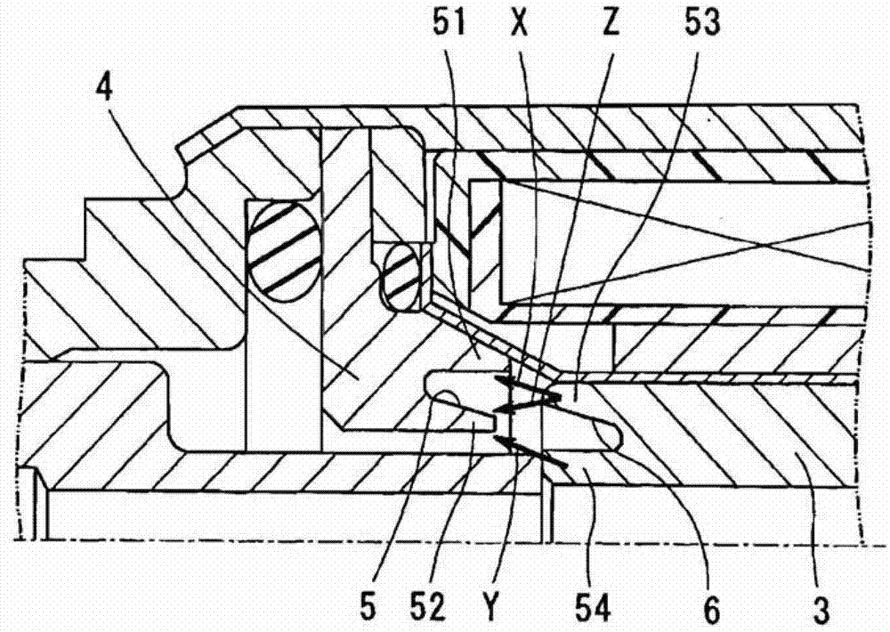
[0083] refer to Figure 4 and 5 , the second embodiment will be described hereinafter. In each of the following embodiments, the same parts and components as those in the first embodiment are denoted by the same reference numerals.
[0084] According to the second embodiment, the sub-stator 55 is provided inside the cup guide 41 to form the stator protrusion 52 . That is, the outer stator protrusion 51 is provided outside the cup guide 41 and the inner stator protrusion 52 is provided inside the cup guide 41 .
[0085] And in the second embodiment, the same advantages as those of the first embodiment can be obtained. In addition, since the inner stator protrusion 52 is provided inside the cup guide 41, the flange portion of the cup guide 41 can be held between the sleeve 21 and the stator 4, so that the O-ring 47 can be sealed in the cup guide 41. Between the inner and outer without another O-ring 46 as shown in the first embodiment.
no. 3 example
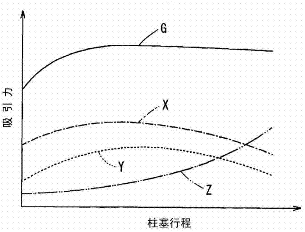
[0087] refer to Figure 6 , 7A and 7B, the third embodiment will be described hereinafter. The electromagnetic actuator 1 has a plunger 3 coaxial with the camshaft.
[0088] The electromagnetic actuator 1 is provided with a coil 2 , a plunger 3 , a stator 4 , a magnetic conduction stator 42 , a yoke 43 and a connector 45 . The magnetically conductive stator 42 is composed of an outer rear stator 42c and an inner rear stator 42d. The yoke 43 is composed of a front yoke 43a and a rear yoke 43b.
[0089] The stator 4 has three stator protrusions. The stator protrusion is an annular protrusion protruding backward from the rear end of the stator 4 . The stator protrusions are composed of: outer stator protrusions 51 having an inner diameter slightly larger than the outer diameter of the plunger 3; inner stator protrusions 52 having an inner diameter smaller than the outer diameter of the plunger 3 and greater than the inner diameter of the plunger 3; The innermost innermost s...
PUM
 Abstract
Description
Claims
Application Information
 - R&D Engineer
- R&D Manager
- IP Professional
- Industry Leading Data Capabilities
- Powerful AI technology
- Patent DNA Extraction
Browse by: Latest US Patents, China's latest patents, Technical Efficacy Thesaurus, Application Domain, Technology Topic, Popular Technical Reports.
© 2024 PatSnap. All rights reserved.Legal|Privacy policy|Modern Slavery Act Transparency Statement|Sitemap|About US| Contact US: help@patsnap.com