[0051] The structural principle and working principle of the present invention will be described in detail below in conjunction with the accompanying drawings:
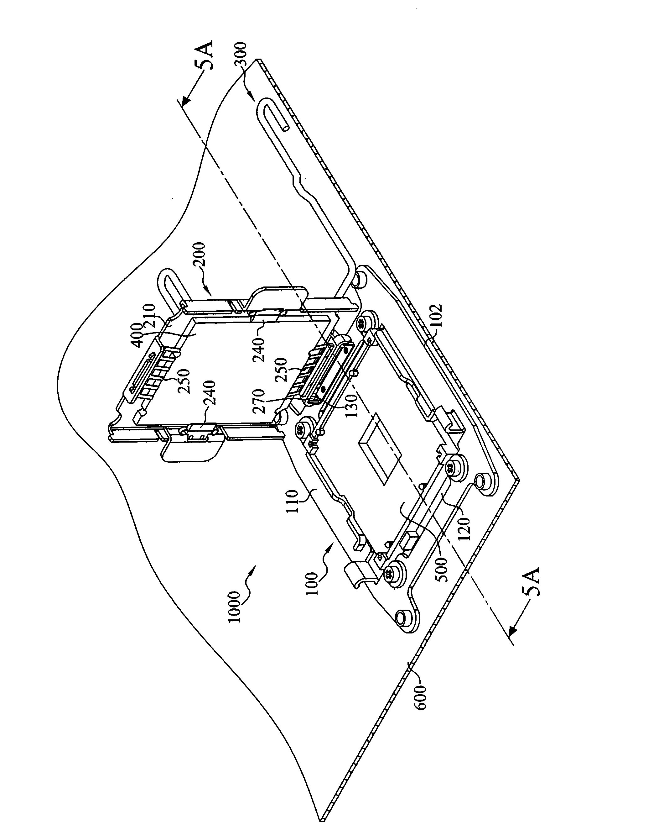
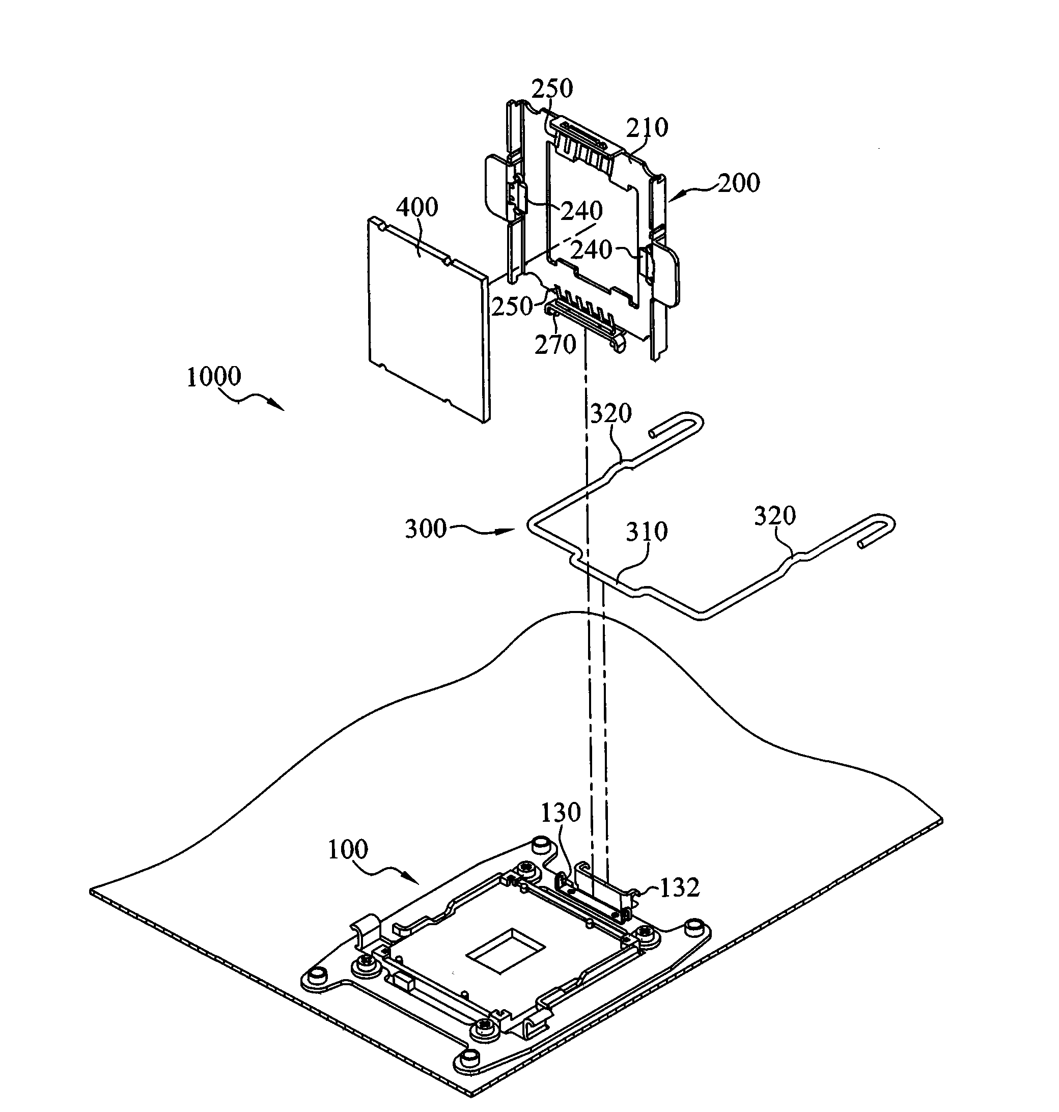
[0052] Please also refer to figure 1 and figure 2 ,among them figure 1 Shown is a schematic structural diagram of a fixing device for a central processing unit according to an embodiment of the present invention, figure 2 For illustration figure 1 Exploded exploded view of the fixing device of the central processing unit. The fixing device 1000 includes a bottom base 100, a carrying cover 200, and a snap assembly 300. Wherein, the bottom base 100 includes a base body 102, a sliding rail 130 and a pivot member 132. The base body 102 has a first surface 110 and a through groove 120, and the through groove 120 is located on the first surface 110; The sliding rail 130 is erected on one side of the first surface 110. The pivot rod 270 of the supporting cover 200 is pivotally connected to the bottom base 100 via the sliding rail 130 and the supporting cover 200 is adapted to pivot around the sliding rail 130 or move along the sliding rail 130. In other words, the pivot rod 270 of the supporting cover 200 can slide linearly in the sliding rail 130 or rotate with a position in the sliding rail 130 as an axis.
[0053] In this embodiment and some other embodiments, the locking assembly 300 has a pivoting portion 310 and two rods 320, and the locking assembly 300 is pivotally connected to the pivoting member 132 of the bottom base 100 through the pivoting portion 310 , And the snap assembly 300 is suitable for fixing the carrying cover 200 on the first surface 110 of the bottom base 100.
[0054] Please also refer to figure 1 and image 3 ,among them image 3 For illustration figure 1 Part of the detailed structure diagram of the bottom base. In this embodiment and some other embodiments, the base body 102 of the bottom base 100 includes a fixing member 170 located at an end corner of the base body 102, and the fixing member 170 is used to fix the bottom base 100 to the host 600 on the board.
[0055] Please also refer to figure 1 , figure 2 and Figure 4 ,among them Figure 4 For illustration figure 1 Partial detailed structure drawing of the carrying cover. In this embodiment and some other embodiments, the carrying cover 200 further includes a carrying body 202 and two elastic fastening elements 240. The carrying body 202 has a second surface 210 and two first retaining walls 220. When the carrying cover When 200 is pivoted to the bottom base 100, the second surface 210 faces the first surface 110, and the first retaining walls 220 are respectively erected on the two opposite sides of the second surface 210 and opposite to each other. The first retaining walls 220 respectively have A through slot 290, the elastic fastening elements 240 are respectively disposed in the through grooves 290, and the elastic fastening elements 240 are adapted to jointly clamp the CPU 400 through elastic deformation.
[0056] In this embodiment and some other embodiments, the elastic fastening element 240 also has two protruding structures 242, respectively located on both sides of the elastic fastening element 240 and extending toward the first retaining wall 220. The protruding structure 242 The elastic deformation can restore the release position of the elastic fastening element 240 to the normal state by the external force. Thereby, when the CPU 400 is pushed in the direction of the slot 290 so that the protruding structure 242 is elastically compressed and deformed, the elastic fastening element 240 presses against the first retaining wall 220 to clamp the CPU 400 together.
[0057] In an embodiment of the present invention, the protruding structure is not used to limit the shape of the protruding structure of the present invention. In other embodiments of the present invention, the structure type is not limited. In other embodiments, other forms can also achieve the effects of the present invention.
[0058] In this embodiment and some other embodiments, the carrying cover 200 further includes two second retaining walls 230 and two fixing elements 250, the second retaining walls 230 are respectively erected on the other two opposite sides of the second surface 210 On the other hand, the fixing elements 250 are disposed on the second retaining wall 230 and opposite to each other. The fixing elements 250 also have a comb-like structure 252 respectively. The comb-like structures 252 respectively extend from the second retaining wall 230 in a direction away from the second surface 210. The shaped structure 252 is suitable for clamping the central processing unit 400. When the bearing cover 200 is pivoted to the bottom base 100, the fixing element 250 abuts the slot 500 so that there is a gap between the bearing cover 200 and the bottom base 100. The CPU 400 will not make contact with the socket 500.
[0059] In an embodiment of the present invention, the comb-like structure is not used to limit the shape of the protruding structure of the present invention. In other embodiments of the present invention, it is not limited to this structure type. In other embodiments, other forms can also achieve the objectives and effects of the present invention.
[0060] According to this embodiment and some other embodiments, two elastic fastening elements 240 and two fixing elements 250 can be used at the same time to clamp the CPU 400 together. When the elastic fastening element 240 and the fixing element 250 clamp the central processing unit 400 together, the second surface 210 of the carrying cover 200 can also abut the central processing unit 400 to maintain the position of the central processing unit 400.
[0061] Please also refer to figure 2 , image 3 and Figure 4 According to this embodiment and some other embodiments, the bottom base 100 includes two buckling portions 160 and the carrier 200 includes two buckling portions 260. The buckling portions 160 and the buckling portions 260 are respectively disposed on the first surface 110 and opposite sides of the second surface 210. The engaging assembly 300 is pivotally connected to the bottom base 100 through the pivoting portion 310 as the axis. The rods 320 are located at both ends of the pivoting portion 310. The engaging assembly 300 is simultaneously engaged with the buckling portions 160 of the bottom base 100 through the rods 320 And the buckling portion 260 of the supporting base 200 fixes the supporting cover 200 to the bottom base 100.
[0062] In an embodiment of the present invention, the buckling portion and the engaging combination are not used to limit the form of the buckling portion and the engaging combination of the present invention. In other embodiments of the present invention, it is not limited to this structure type. .
[0063] Please also refer to image 3 and Figure 4 In this embodiment and some other embodiments, the carrier body 202 further includes two guiding grooves 272 and the base body 102 further includes two guiding blocks 150. The guide block 150 is erected on one side of the first surface 110 and corresponds to the guide groove 272. When the engaging assembly 300 is engaged with the carrying cover 200 to the bottom base 100, the guide block 150 is correspondingly engaged with the guide groove 272. In this way, the guiding groove 272 and the guiding block 150 can limit and guide the supporting cover 200 to engage the bottom base 100 in a straight up and down manner.
[0064] The following will introduce a fixing device to fix a CPU in a slot, please refer to Figure 5A , Figure 5B and Figure 5C , Figure 5A For illustration figure 1 The action exploded view of the 5A-5A section line, Figure 5B and Figure 5C This is an exploded view of actions according to an embodiment of the present invention. In this embodiment, the fixing member 170 of the bottom base 100 is first used to fix the main board 600, and the through slot 120 is provided in the slot 500 so that the slot 500 penetrates through the slot 120. Then, the CPU 400 is fastened to the elastic fastening element 240 and the fixing element 250, so that the elastic fastening element 240 and the fixing element 250 are elastically deformed to respectively clamp the opposite ends of the CPU 400, thereby using the material itself The flexibility of the central processing unit 400 is fixed to the carrying cover 200. The bearing cover 200 is pivoted with the sliding rail 130 as the axis, and the pivot rod 270 is located at the position A of one end of the sliding rail 130 at this time. When the first surface 110 and the second surface 210 face each other, the carrying cover 200 is extended along the sliding rail 130 and toward the bottom base 100, so that the comb structure 252 of the fixing element 250 contacts the slot 500, and is pivotally connected at this time The rod 270 is located between the position A and the position B of the sliding rail 130 after sliding. At this time, the CPU 400 and the socket 500 have a gap due to the comb structure 252 elastically pressing against the edge of the socket 500, so that the CPU 400 and the socket 500 are not in contact due to the gap. Finally, the bearing cover 200 is rotated and pressed against the bearing cover 200 and the base base 100 through the rod 320 of the clamping assembly 300 with the pivot rod 310 as the axis. The rod 320 then buckles the fastening portion 160 and the fastening portion 260 and The guiding blocks 150 engage the guiding grooves 272 correspondingly, so that the CPU 400 on the supporting cover 200 can contact the socket 500. At the same time, the pivot rod 270 slides to the position B of the other end of the sliding rail 130, so that the CPU 400 can be completely fixed to the socket 500. In this embodiment, the B position is closer to the bottom base 100 than the A position.
[0065] Based on the above-mentioned embodiments, after the CPU is fixed to the carrying cover by the elastic fastening element and the fixing element, it is first rotated above the bottom base, and at the same time, the elasticity of the fixing element is used to maintain the CPU above the bottom base without directly Enter into the slot, and then press the central processing unit with the carrying cover to the bottom base with a straight-up and straight-down slide rail, plus the guide groove and the limit guide of the guide rail, before entering the slot vertically. In this way, the bending and damage of the pins in the socket caused by the angle caused by the rotation are avoided, the effect of the central processing unit being fully contacted with the socket and the maintenance cost and time problems caused by damage of the socket are avoided.
[0066] Of course, the present invention can also have various other embodiments. Without departing from the spirit and essence of the present invention, those skilled in the art can make various corresponding changes and modifications according to the present invention, but these corresponding All changes and deformations shall belong to the protection scope of the appended claims of the present invention.