Light emitting diode and manufacturing method thereof

A technology of light-emitting diodes and manufacturing methods, which is applied in the direction of electrical components, electric solid devices, circuits, etc., can solve the problems of single installation method and poor installation adaptability, and achieve strong installation adaptability, installation methods and various installation postures.

Inactive Publication Date: 2013-03-27
ZHANJING TECH SHENZHEN +1
View PDF4 Cites 3 Cited by
  • Summary
  • Abstract
  • Description
  • Claims
  • Application Information

AI Technical Summary

Problems solved by technology

When this light-emitting diode is installed on the circuit board, generally the substrate can only be installed facing the circuit board, the installation method is single, and the installation adaptability is poor.

Method used


Image

  • Light emitting diode and manufacturing method thereof
  • Light emitting diode and manufacturing method thereof
  • Light emitting diode and manufacturing method thereof

Examples


Embodiment Construction

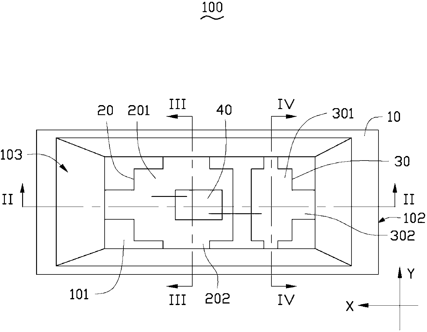
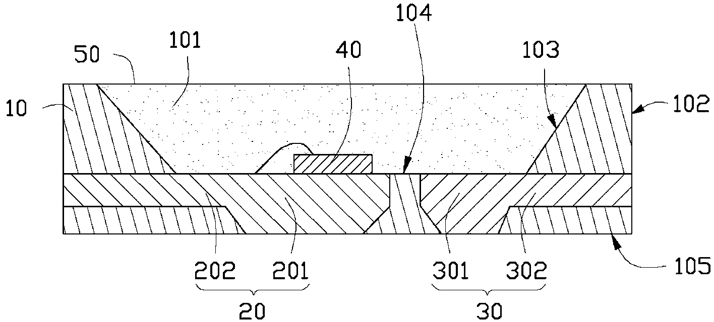
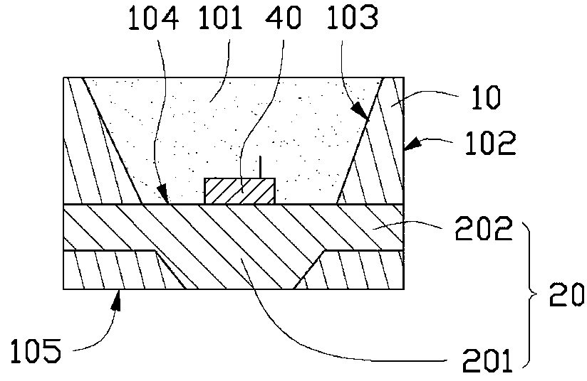
[0029] Figure 1 to Figure 5 Shows the light emitting diode 100 in the first embodiment of the present invention, the light emitting diode 100 includes a base 10, a first electrode 20 embedded on the base 10, a second electrode 30, and the A light-emitting chip 40 electrically connected to the first and second electrodes 20 and 30 .

[0030] The base 10 is approximately rectangular parallelepiped, with an inverted trapezoid-shaped groove 101 in the center. The base 10 includes four outer sides 102 , four inner sides 103 , an inner bottom 104 and an outer bottom 105 . The four inner sides 103 surround the groove 101 and the light-emitting chip 40 , and the inner bottom surface 104 is located at the bottom of the groove 101 . The base 10 is made of reflective material, such as epoxy resin, silicone resin or polyphthalamide (PPA), etc., and the four outer surfaces 102 are respectively facing four sides of the base 10 . Both the inner surface 103 and the inner bottom surface 104...


PUM


Abstract

A light emitting diode comprises a base, a first electrode, a second electrode and a light emitting chip. The first electrode and the second electrode are arranged on the base, and the light emitting chip is electrically connected with the first electrode and the second electrode. The first electrode comprises a first body and a plurality of first supporting electrodes, wherein the first supporting electrodes extend outwards from the first body; and the second electrode comprises a second body and a plurality of second supporting electrodes extending outwards from the second body. The first supporting electrode and the second electrode are exposed from the outside of the base; at least one first supporting electrode and one second supporting electrode are exposed from the opposite side of the base, and at least one first supporting electrode and at least one second supporting electrode are exposed from the same side of the base. The light emitting diode can be installed by different manners and at different positions, and accordingly has high installation adaptability. The invention further discloses a manufacturing method of the light emitting diode.

Description

technical field [0001] The invention relates to the field of semiconductor lighting, in particular to a light emitting diode and a manufacturing method of the light emitting diode. Background technique [0002] As a new light source, light-emitting diodes have been widely used in many occasions and have a tendency to replace traditional light sources. [0003] Existing light-emitting diodes generally include a substrate, two electrodes disposed on the upper surface of the substrate, an LED chip disposed on one of the electrodes, and a packaging body packaged on the electrode and the LED chip. The two electrodes protrude to opposite sides of the package body and extend to the lower surface of the substrate, so as to facilitate mounting of the LED and the circuit board. When this light emitting diode is installed on the circuit board, generally the substrate can only be installed facing the circuit board, the installation method is single, and the installation adaptability is...

Claims


Application Information

Patent Timeline
Patent Type & Authority Applications(China)
IPC IPC(8): H01L33/48H01L33/62H01L33/00
CPCH01L24/97H01L33/486H01L33/62H01L2224/48091H01L2224/48247H01L2224/97H01L2924/01322H01L2924/12041H01L2924/00014H01L2924/00H01L2224/85
Inventor 陈滨全林新强
Owner ZHANJING TECH SHENZHEN
Why Eureka
Try Eureka