Ventilated vacuum well for sewage tank

A ventilated and sewage tank technology, applied in the direction of sewage removal, water/sewage treatment, water/sludge/sewage treatment, etc., can solve problems such as large safety hazards, high input costs, and complex structure and functions

Pending Publication Date: 2020-10-23
QINGHUAN TUODA (SUZHOU) ENVIRONMENTAL TECH CO LTD
View PDF10 Cites 2 Cited by
  • Summary
  • Abstract
  • Description
  • Claims
  • Application Information

AI Technical Summary

Problems solved by technology

[0018] The purpose of the present invention is to provide a sewage tank ventilated vacuum well to solve the problems of complex structure and function, large safety hazard, poor reliability and high investment cost in the vacuum well in the prior art.

Method used


Image

  • Ventilated vacuum well for sewage tank
  • Ventilated vacuum well for sewage tank
  • Ventilated vacuum well for sewage tank

Examples


Embodiment 1

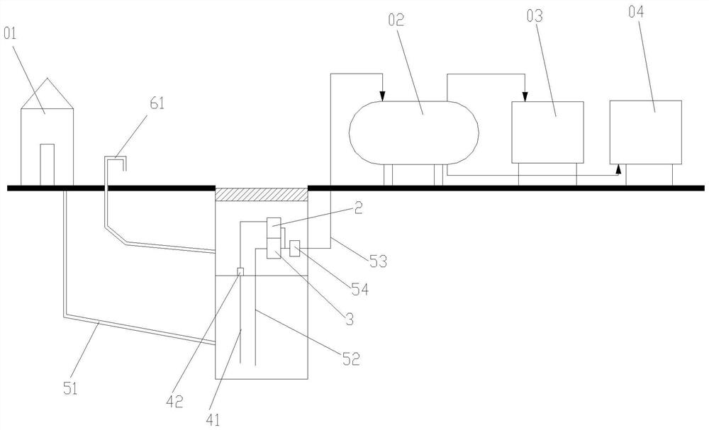
[0089] Such as figure 1 As shown, a sewage tank ventilated vacuum well, its application scenario is:

[0090] The ventilated vacuum well of the sewage tank is set below the ground as a temporary sewage collection and storage device, which will come from the sewage source 01 (such as rural bungalows, tile houses, buildings, cement houses, villas, and urban residential buildings, high-rise buildings, buildings, etc.) The domestic sewage (such as black water represented by waste water sources such as urinals and toilets, and gray water represented by waste water sources such as kitchen, washing and bathing) is transported to a remote sewage treatment station 04, and the sewage tank is ventilated vacuum A vacuum collection tank 02 and a vacuum pump station 03 are also arranged between the well and the sewage treatment station 04 .

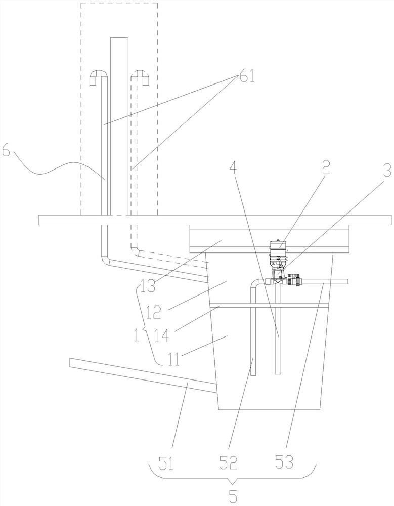
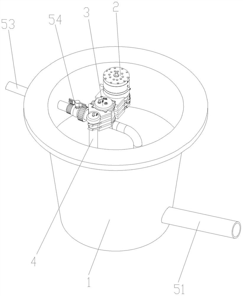
[0091] Such as figure 2 As shown, the sewage tank ventilated vacuum well includes a well body 1, a pneumatic controller 2 installed in the well bod...

Embodiment 2

[0113] Such as Figure 12 As shown, a sewage tank ventilated vacuum well, its application scene is the same as that of embodiment 1. In this embodiment, the way of laying the gravity sewage inlet pipeline 51 is to carry out gravity from the sewage source to the vacuum well according to the gradient of gravity drop. Pipe layout, if the distance is too large, a necessary number of lifting elbows 55 needs to be added therebetween. When there are lifting elbows 55, the sewage accumulated at the lifting elbows 55 will cause air in the ground ventilation pipe 61 near the building. If it cannot be effectively entered into the sewage chamber 11, the problem of water resistance will appear at this time.

[0114] The impact of the water resistance is as follows:

[0115] One, since the sewage chamber 11 and the equipment chamber 12 are configured in a sealed manner, the air above the sewage chamber 11 is in a sealed state; When the air is connected, the pressure of the air above the s...

Embodiment 3

[0123] Such as Figure 18 As shown, a sewage tank ventilation type vacuum well, its application scene is the same as embodiment 1 and embodiment 2, in this embodiment, such as Figure 19 , Figure 20 As shown, the liquid level sensor 4 and the pressure relief device 7 in Embodiment 2 are designed in one body, and the pressure relief device 7 is installed on the partition 14, as Figure 21 , Figure 22 As shown, its structure includes a pressure relief housing 71, a vent assembly 72 and a sealing assembly 73 arranged in the pressure relief housing 71, the lower end of the pressure relief housing 71 is provided with a pipe body 43 extending to the lower end of the sewage chamber 11; the liquid level The sensor 4 includes a liquid level circulation pipeline 41 and a liquid level sensor interface B42, wherein the liquid level circulation pipeline 41 is set through the pressure relief housing 71, and the liquid level sensor interface B42 communicates with the upper end of the liq...


PUM


Abstract

The invention relates to a ventilated vacuum well for a sewage tank. The ventilated vacuum well is used for collecting sewage at a sewage source and discharging the sewage into a downstream sewage treatment pipe network. The ventilated vacuum well comprises a well body, a pneumatic controller, a vacuum blow-down valve, a liquid level sensor, a sewage pipeline system and a ventilation pipeline system, wherein the pneumatic controller, the vacuum blow-down valve and the liquid level sensor are arranged in the well body, and the sewage pipeline system and the ventilation pipeline system are connected with the well body; the liquid level sensor is used for sensing the rise and fall of water level so as to drive the pneumatic controller to drive the vacuum blow-down valve to work, the pneumaticcontroller can be used for ventilation, water collection and drainage, and the integral structure is compact; and a gravity sewage inlet pipeline is arranged in the sewage pipeline system. When the ventilation pipeline system is connected with the gravity sewage inlet pipeline, a lifting bent pipe is arranged on the gravity sewage inlet pipeline to generate water resistance, so a pressure reliefdevice is arranged. The pressure relief device is used for ventilation of the vacuum blow-down valve and the pneumatic controller, pressure relief of air in the upper part of a sewage chamber and drainage. The tolerance of water resistance of the gravity sewage inlet pipeline is improved.

Description

technical field [0001] The invention relates to the technical field of vacuum sewage continuous collection, temporary storage and periodic delivery system. The vacuum sewage continuous collection, temporary storage and periodic delivery system is a vacuum well system, which has temporary sewage collection using vacuum sewage valve for periodic sewage discharge tank, and can transport the sewage in its sewage collection tank to the downstream vacuum collection pipeline network, which is controlled by the control device of the differential pressure drive control method. Its components generally include vacuum drain valves, sewage tanks, equipment tanks, Manhole cover, manual ball valve, gravity sewage inlet pipeline, sewage pipeline connected to the downstream vacuum collection pipeline network, sewage suction pipeline, for this technical field, the present invention particularly relates to a sewage tank ventilated vacuum well. Background technique [0002] In the field of liq...

Claims


Application Information

Patent Timeline
Patent Type & Authority Applications(China)
IPC IPC(8): E03F1/00E03F5/04E03F5/22E03F7/00E03F3/02F16K31/126E03F5/14
CPCE03F1/00E03F1/006E03F3/02E03F5/0401E03F5/14E03F5/22E03F7/00F16K31/1268
Inventor 崔利兴邓永峰黄森辰
Owner QINGHUAN TUODA (SUZHOU) ENVIRONMENTAL TECH CO LTD
Why Eureka
Try Eureka