Wireless communication system and base station
A wireless communication system and wireless signal technology, applied in wireless communication, electrical components, sustainable buildings, etc., can solve problems such as throughput reduction and communication disconnection, and achieve the goal of suppressing communication, reducing uplink interference, and stabilizing wireless communication. Effect
- Summary
- Abstract
- Description
- Claims
- Application Information
AI Technical Summary
Problems solved by technology
Method used
Image
Examples
Embodiment 1
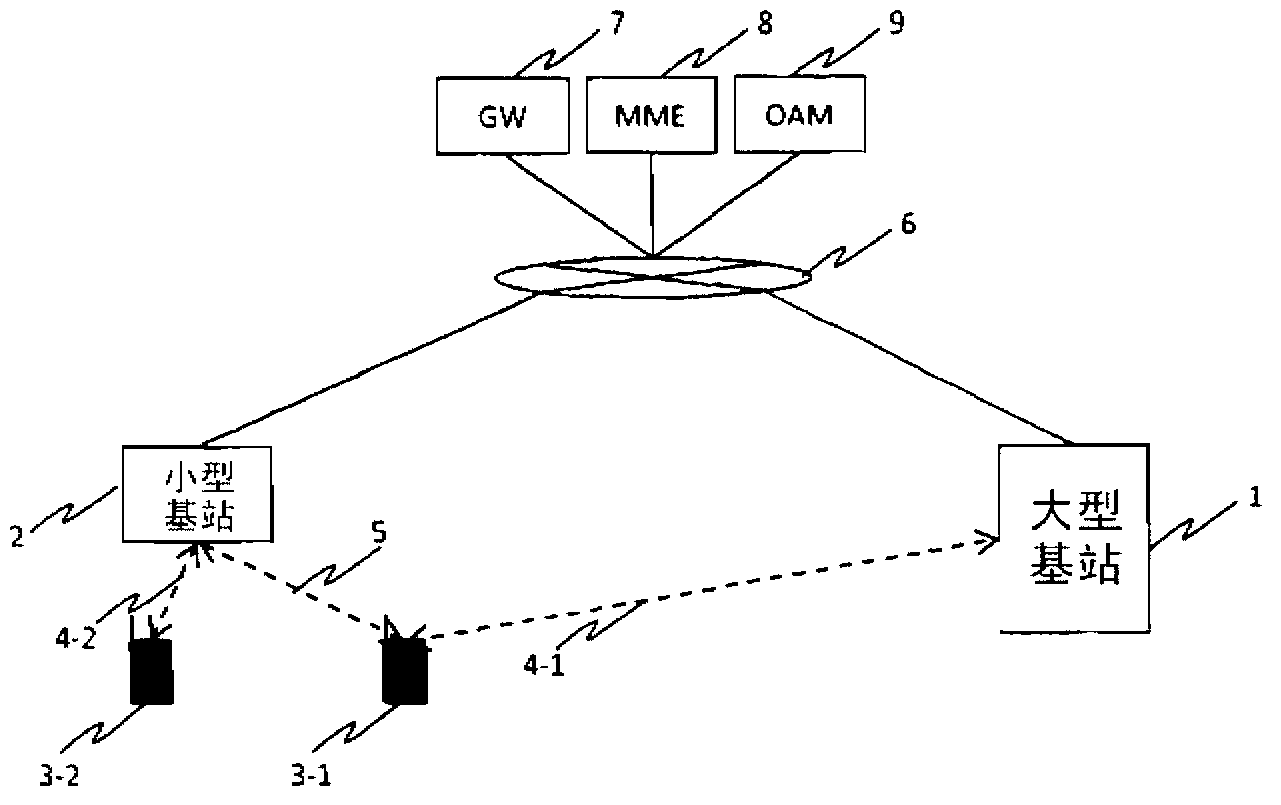
[0087] figure 1 An example of the system configuration of this embodiment is shown. As the base station device of the wireless communication system, there are a large base station (first base station) 1 with relatively high transmission power and a small base station (second base station) 2 with low transmission power. For example, a terminal 3-1 establishes a connection with the large base station 1, The terminal 3 - 2 establishes a connection with the small base station 2 and is in a state where data communication can be performed ( 4 - 1 , 4 - 2 ). The data communication 4 - 1 between the terminal 3 - 1 and the macro base station 1 becomes an interference signal 5 for the small base station 2 . In addition, in this embodiment, the larger the transmission power difference between the base station devices, the more obvious the problem to be solved in this embodiment. Therefore, the large base station 1 and the small base station 2 are distinguished by transmission power, but...
Embodiment 2
[0204] In the above-mentioned first embodiment, the method of multicasting the interference rule information from the small base station to nearby base stations was described, but in this embodiment, the method of multicasting to nearby base stations only when large interference occurs is described. .
[0205] exist Figure 5 In the flow chart of the small base station shown, in the interference rule extraction process performed in S1005, it is not estimated Figure 8A or Figure 8B The parameters shown in 404 to 407 are only used to judge whether interference with a large received power is detected during the interference measurement period, and if interference is detected, a multicast message is sent to nearby base stations. In addition, a multicast message may be communicated when a predetermined number of times of interference with a large reception power is detected within the interference measurement time. When the multicast message arrives, the nearby base stations k...
Embodiment 3
[0210] In the first embodiment, Figure 14 and Figure 16 Small base stations and large base stations are described separately, but each base station may also have Figure 14 and Figure 16 The function of both sides of the base station. That is, there may be a small base station that collectively has the function of a macro base station, and a macro base station that collectively has the function of a small base station. The purpose is that even if all base stations have the same downlink transmission power, as long as there are base stations that have both functions, the effects of this embodiment will be obtained. Those skilled in the art can easily design a base station having both functions. In addition, by adopting the same design for all base stations, development costs can be reduced, and as a result, cost reduction effects for base stations can be obtained.
PUM
 Abstract
Description
Claims
Application Information
 - R&D
- Intellectual Property
- Life Sciences
- Materials
- Tech Scout
- Unparalleled Data Quality
- Higher Quality Content
- 60% Fewer Hallucinations
Browse by: Latest US Patents, China's latest patents, Technical Efficacy Thesaurus, Application Domain, Technology Topic, Popular Technical Reports.
© 2025 PatSnap. All rights reserved.Legal|Privacy policy|Modern Slavery Act Transparency Statement|Sitemap|About US| Contact US: help@patsnap.com


