Power Module Fixing Mechanism

A technology of power supply module and fixing mechanism, which is applied to the circuit layout of the supporting structure, the components of the casing/cabinet/drawer, elastic/clamping device, etc., which can solve the problems of increased transportation costs, waste of space, and unfavorable users operation and other issues to achieve the effect of simplifying removal or insertion

Active Publication Date: 2016-08-03
DELTA ELECTRONICS (SHANGHAI) CO LTD +1
View PDF4 Cites 0 Cited by
  • Summary
  • Abstract
  • Description
  • Claims
  • Application Information

AI Technical Summary

Problems solved by technology

[0004] In the above structure, both the handle 11 and the hook 15 protrude from the front cover 6 of the power module body 5, resulting in waste of space and increased transportation costs
Moreover, when the hook 15 loses its elasticity, the protrusion 16 cannot be firmly connected to the through hole 18, and the power module body 5 cannot stably supply power to the electronic device.
Also, due to the size limitation of the power module 5 itself, when the size of the handle 11 is small, it will be unfavorable for users with thicker fingers to operate, resulting in inconvenience in use

Method used


Image

  • Power Module Fixing Mechanism
  • Power Module Fixing Mechanism
  • Power Module Fixing Mechanism

Examples


Embodiment Construction

[0060] The preferred embodiments of the present invention are described hereby in conjunction with the accompanying drawings.

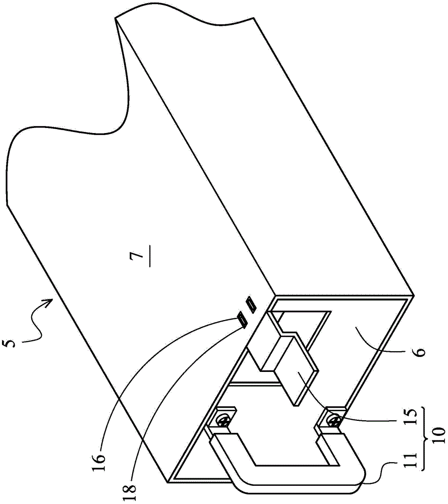
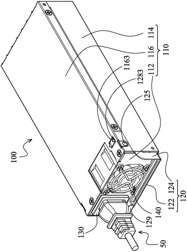
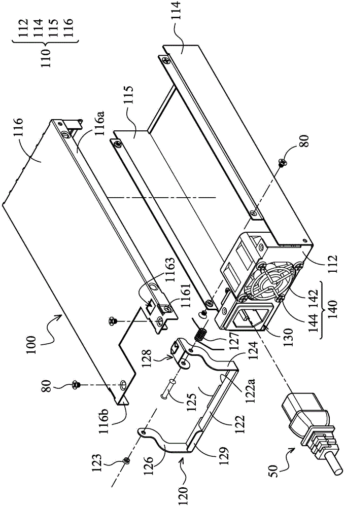
[0061] see figure 2 and image 3 , figure 2 A schematic diagram showing that the power module fixing mechanism 100 of the present invention is connected to a plug 50, wherein the operating lever 120 is located at a first position; image 3 In , the electronic components inside the power module body 110 are omitted from drawing, and are indicated here in advance.

[0062] The power module fixing mechanism 100 of the present invention includes a power module body 110 , an operating lever 120 , a socket 130 and a fan component 140 . In a specific embodiment, the power module body 110 is a rectangular structure, including a front cover 112 , two side covers 114 and 115 and a top cover 116 . The two side covers 114 and 115 are respectively adjacent to the left and right sides of the front cover 112 and opposite to each other. The upper cover 116 is ...


PUM


Abstract

The invention provides a power supply module fixing mechanism which comprises a power supply module body and an operating rod. The power supply module body comprises a front cover and an upper cover adjacent to the front cover, and the operating rod is pivoted to at least one side of the upper cover and is attached to the front cover when positioned at a first position. The operating rod of the power supply module mixing mechanism provides a convenient holding mode for a user, and a procedure of removing the power supply module body from an electronic device is simplified. In addition, by the aid of the relative configuration relationship between the operating rod and a socket, a safe uninterruptible power mechanism is more effectively provided for the electronic device.

Description

technical field [0001] The invention relates to a power module fixing mechanism, in particular to a power module fixing mechanism which is convenient for users to operate. Background technique [0002] Generally speaking, electronic equipment must rely on a power supply module to maintain the operation of the electronic equipment. For example, a power converter (adaptor) is one of the common power modules, which converts the input voltage into various operating voltages required for its operation. [0003] See figure 1 , in order to facilitate its disassembly, the traditional power module is generally designed with a disassembly device 10 . The dismounting device 10 includes a handle 11 and a hook 15 . The handle 11 is disposed on the front cover 6 of the power module body 5 for the user to hold. The hook 15 is usually a Z-shaped shrapnel, one end of the hook 15 protrudes from the front cover 6 of the power module body 5, and the other end of the hook 15 is arranged insi...

Claims


Application Information

Patent Timeline
Patent Type & Authority Patents(China)
IPC IPC(8): H05K5/02H05K7/12
Inventor 李岱
Owner DELTA ELECTRONICS (SHANGHAI) CO LTD
Why Eureka
Try Eureka