

wiper device
A wiper and wiper technology, which is applied in transportation and packaging, vehicle cleaning, vehicle maintenance, etc., can solve the problem of positioning the wiper shaft, the size and/or position of the wiper range of the wiper is not optimal, etc.
Inactive Publication Date: 2016-01-20
ROBERT BOSCH GMBH
View PDF4 Cites 0 Cited by
- Summary
- Abstract
- Description
- Claims
- Application Information
AI Technical Summary
Problems solved by technology
The disadvantage here is that the space required for the installation of the wiper device in the motor vehicle makes optimal positioning of the wiper shaft relative to the view glass problematic
Especially when using a wiper device in the area of the windshield of a motor vehicle, the distance from the wiper shaft or the other wiper shaft to the side boundary (A-pillar) of the windshield is relatively large due to the installation space, so that the wiper (which utilizes the wiper arm to connect to the wiper shaft) the wiper reach is not optimal in size and / or location
Method used
View moreImage
Smart ImageViewing Examples

Examples
Embodiment Construction
Login to View More PUM
 Abstract
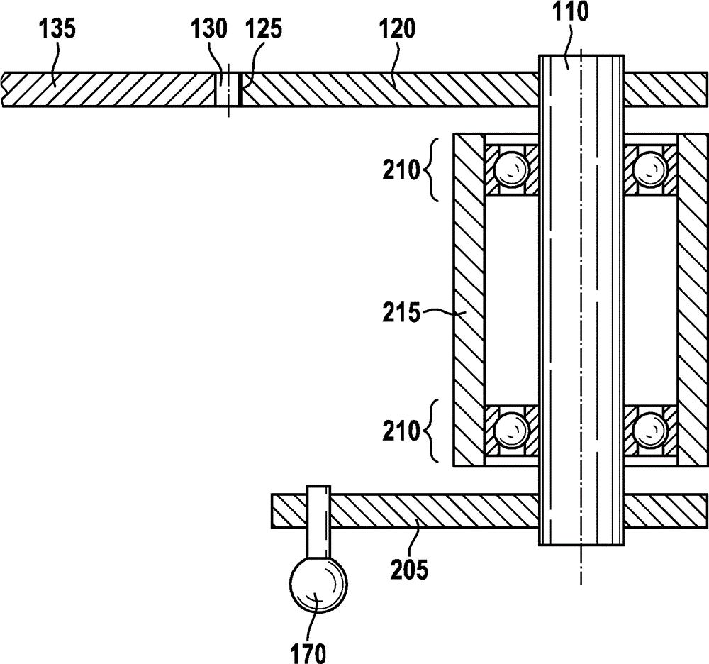
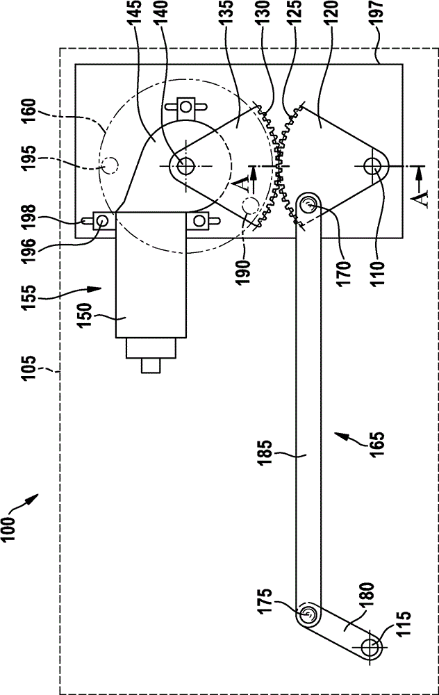
The invention relates to a wiper device (100) for use in a motor vehicle comprising a wiper shaft (110) for driving a wiper arm in oscillation, a reversible drive motor (155), and a transmission unit for transmitting the motion of the drive motor to the wiper shaft. The transmission unit comprises a gear segment (120) mounted on the wiper shaft, with which a gear or further gear segment (135) that is mounted on the drive motor engages.
Description
technical field The invention relates to a windshield wiping device having the features stated in the preamble of claim 1 . Background technique Windshield wiper devices are used, for example, in motor vehicles to guide a wiper blade over a windshield and to keep the windshield clear of dirt and moisture. The wiper blade is driven here by a wiper arm which pivots back and forth about a wiper shaft. Many different devices are known for the pivotal drive of the wiper shaft, which differ in particular with regard to their complexity and installation space requirement. In typical exemplary embodiments, the electric motor is connected to the wiper shaft by means of a coupling drive. The first crankshaft connected to the output shaft of the motor acts on the second crankshaft connected to the wiper shaft through a push rod, thereby converting the rotational motion of the output shaft of the motor into the swing motion of the wiper shaft. A further wiper shaft can be provided f...
Claims
Login to View More Application Information
Patent Timeline
 Patent Type & AuthorityPatents(China)
IPC IPC(8): B60S1/26B60S1/24
CPCB60S1/26B60S1/24
InventorL.特伦克勒
OwnerROBERT BOSCH GMBH