Horizontally revolvable toolbox

A technology of plane rotation and tool box, which is applied in the field of tool boxes, can solve the problems of increasing the space for placing tools, fewer tools, and single function, and achieve the effect of intuitive display, convenient tool picking and placing, and increasing the volume of tool placement

Active Publication Date: 2013-04-03
HANGZHOU UNITED TOOLS CO LTD +1
View PDF14 Cites 6 Cited by
  • Summary
  • Abstract
  • Description
  • Claims
  • Application Information

AI Technical Summary

Problems solved by technology

[0008] The present invention solves the defect that the existing tool box has only one layer, the function is relatively single, and the tools that can be placed are few, and provides a multi-layer plane rotating tool box. Increase space for placing tools
[0009] The present invention also solves the defect that the existing tool box uses translation to expand the stacked box parts, but the upper box part is easy to block the lower box part, which makes it inconvenient to pick and place tools. It provides a horizontal rotation method that can completely Expose the lower tool storage space for easy tool access
[0010] The present invention also solves the problem that the existing tool box adopts the method of lifting up to separate stacked boxes, but the gap between the boxes is small, it is inconvenient to pick and place the tools, and the upper box will block the lower box The defect is to provide a flat rotating tool box, which rotates in a horizontal plane. After the upper box body is rotated, it can completely expose the lower tool storage space, and the upper box body will not block the tools in the lower box body.

Method used


Image

  • Horizontally revolvable toolbox
  • Horizontally revolvable toolbox
  • Horizontally revolvable toolbox

Examples


Embodiment 1

[0044] Embodiment 1: a kind of plane rotation tool box (see attached figure 1 ), including a quadrangular fixed box body 3 and a quadrangular movable box body 7, the fixed box body and the movable box body are in matching shapes and sizes, and both the fixed box body and the movable box body are blow molded at one time.

[0045] One side of the fixed box is hinged with a handle 10, and the other side of the fixed box is hinged with a flip 1 through a hinge 2, and the shape of the flip matches the size and shape of the fixed box. Both sides of the handle on the fixed box body are provided with an inner concave portion 6, and the inner concave portion is provided with a locking toggle 5, and the corresponding side of the movable box body is also provided with an inner concave portion 6, and the inner concave portion on the fixed box body is connected with the movable The inner recesses on the box body correspond to each other, and the position corresponding to the inner recesses...

Embodiment 2

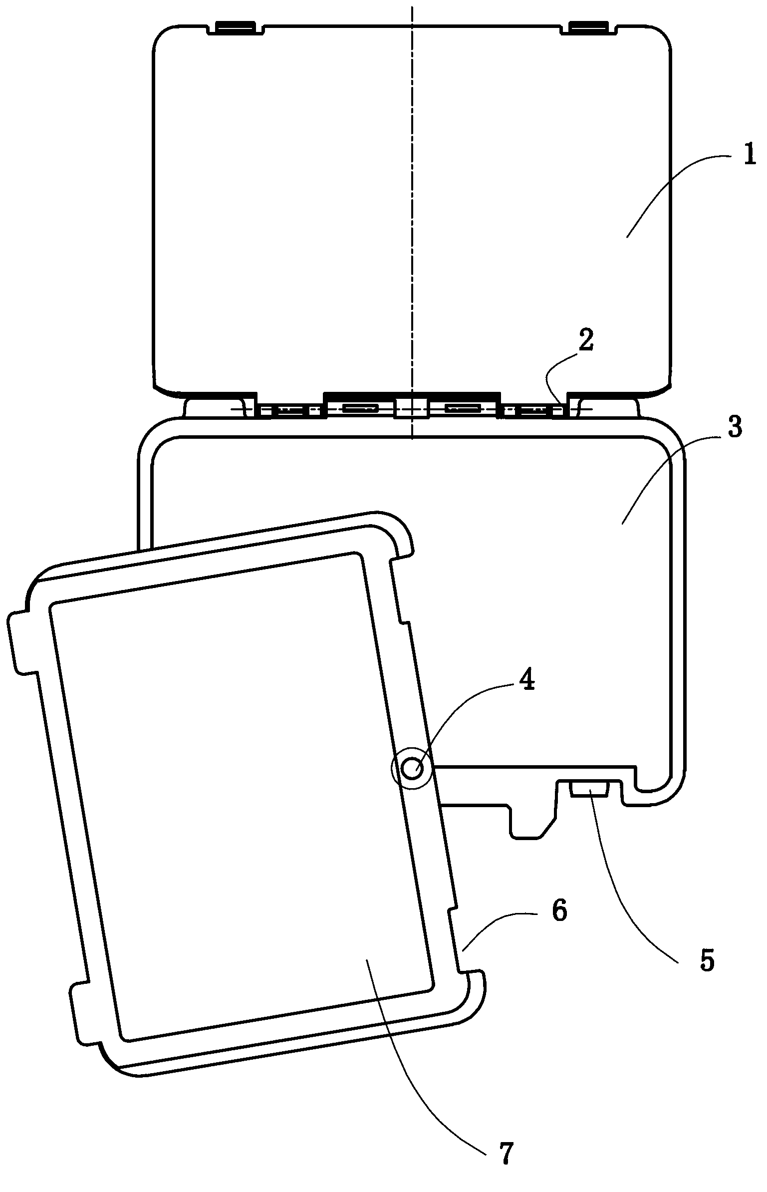
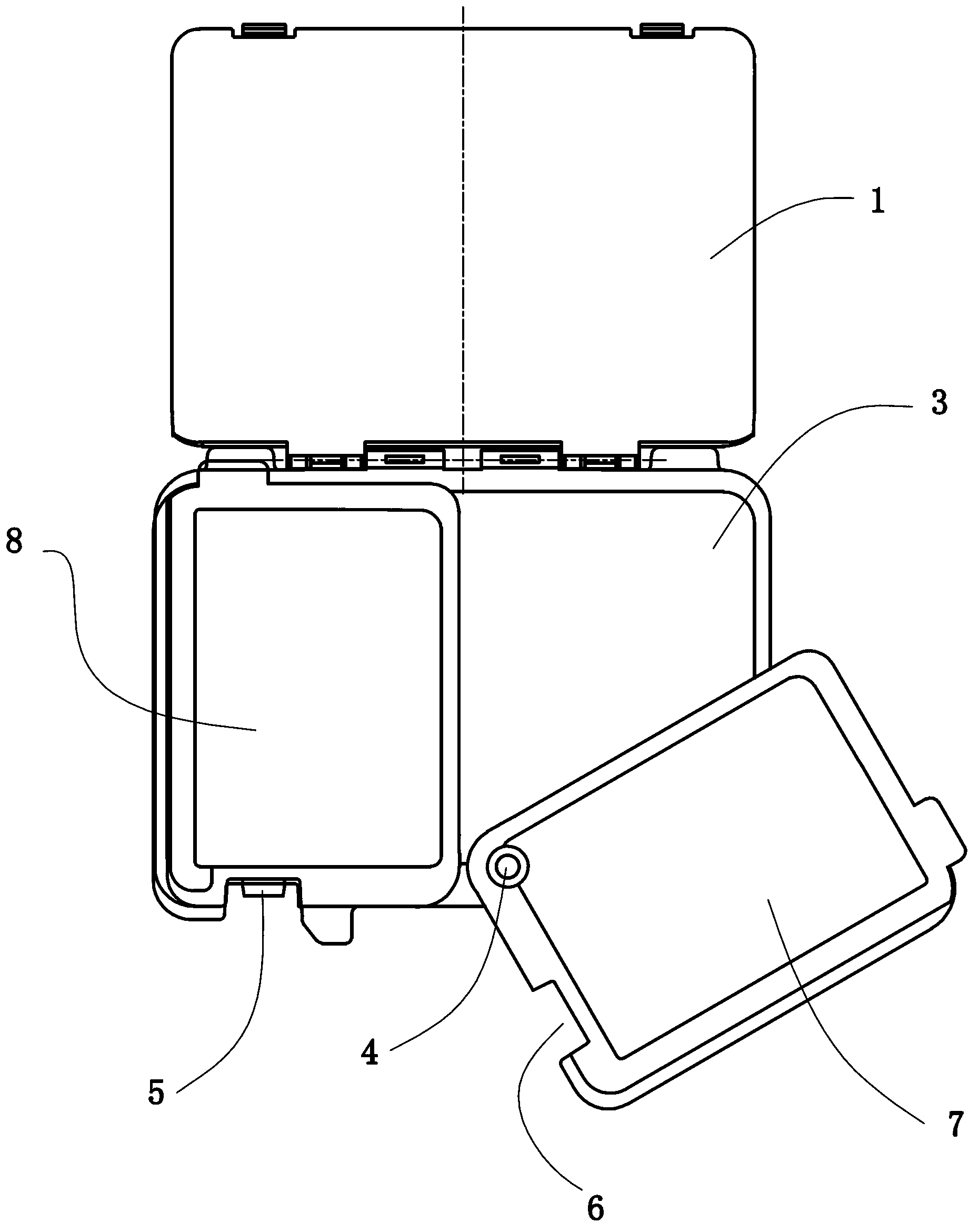
[0048] Embodiment 2: a kind of plane rotation tool box (see attached figure 2 ), including the fixed box body 3 and the movable box body 7, the fixed box body is in the shape of a ladder, and the part of the fixed box body that is one step higher becomes the raised part 8 of the fixed box body, and the outer dimension of the movable box body is lower than that of the fixed box body The outer dimensions of the stepped surfaces of the first stage are the same, and the thickness of the movable box body is the same as the height difference between the upper stepped surface of the fixed box body and the lower stepped surface of the fixed box body. The area of ​​the raised portion is equal to that of the movable box and is half of the area of ​​the fixed box. A through hole is provided at the corner of the movable box body, and the same through hole is provided at the position corresponding to the through hole of the movable box body near the side of the fixed box body. The rotati...

Embodiment 3

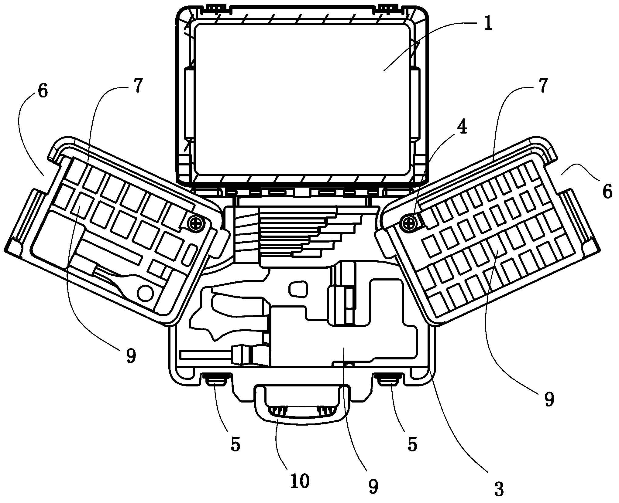
[0050] Embodiment 3: a kind of plane rotation tool box (see attached image 3 attached Figure 4 attached Figure 5 attached Figure 6 ), including a quadrangular fixed box 3 and two quadrangular movable boxes 7, the sum of the areas of the two movable boxes is equal to the area of ​​the fixed box, and both the fixed box and the movable box are blow molded at one time. The two movable boxes are on the same layer and both are above the fixed box. The corners of the movable box are provided with through holes, and the corners of the fixed box are provided with through holes. The through holes on the fixed box are close to the side where the hinge 2 is located. The movable box and the fixed box are connected by a rotating shaft 4 .

[0051] The periphery of the through hole is provided with a groove 13 on the fixed box body, and the groove is in the shape of an arc with the axis of the rotating shaft as the center of the circle. After the fixed box body is connected, the pro...


PUM


Abstract

The invention relates to a horizontally revolvable toolbox, which solves the defects in the prior art that the conventional toolbox has only one layer and only one function, and the number of tools capable of being placed in the conventional toolbox is small. The horizontally revolvable toolbox comprises a fixed box body and at least one movable box body, both the fixed box body and the movable box body are provided with tool-holding spaces, the movable box body is connected with the fixed box body through a rotary shaft, the rotary shaft is perpendicular to the planes of the fixed box body and the movable box body, and the movable box body can be revolved around the rotary shaft within the plane of the movable box body. Since the fixed box body and the movable box body are arranged at different layers, the tool-holding capacity of the toolbox is expanded, and complex tools and various accessories can be placed in the toolbox; since the movable box body can be revolved around the vertical rotary shaft within the plane of the movable box body and can expose the covered tool-holding space, tools can be conveniently taken out and placed; moreover, after the movable box body is revolved relative to the fixed box body, all the tools in the toolbox can be shown, sight cannot be blocked, and therefore the toolbox has a visual showing effect.

Description

technical field [0001] The invention relates to a tool box, in particular to a plane rotating tool box whose inner box body can rotate in its own plane. Background technique [0002] With the standardization requirements of the work in various industries, the operation accuracy requirements in the work process are getting higher and higher, and more and more tools and equipment are used during work, which brings inconvenience to the staff. These tools include various instruments and supporting accessories, and there are many types and quantities. In order to meet different functions, the sizes of the tools are also different. If it is placed randomly, there is no tool box to put it together, it is messy, it is inconvenient to find, and it is impossible to protect the equipment or accessories, and these tools are easily damaged. Especially for an industry with special requirements, such as the medical industry, there are special requirements for the placement of equipment, a...

Claims


Application Information

Patent Timeline
Patent Type & Authority Applications(China)
IPC IPC(8): B25H3/02
Inventor 池晓蘅
Owner HANGZHOU UNITED TOOLS CO LTD
Why Eureka
Try Eureka