Pump

A pump body and cavity technology, which is applied in the field of conveying devices that increase fluid pressure, can solve the problems of small fugitive dust, large oil pump pressure, small flow rate, etc., and achieve the effects of small pulsation, large dust, and small wear of parts

Inactive Publication Date: 2013-04-03
秦永
View PDF0 Cites 12 Cited by
  • Summary
  • Abstract
  • Description
  • Claims
  • Application Information

AI Technical Summary

Problems solved by technology

[0002] At present, the pumps on the market are divided into water pumps, oil pumps and air pumps. The flow rate of the water pump is large, but the outlet pressure is small, the dust of the single machine is small, and the cavitation allowance is large. In order to obtain the work of high dust and large flow, people have to adopt multi-pole pump, which will reduce the overall efficiency of the pump unit and increase the cost of use; while the oil pump has the disadvantages of high pressure, small flow, and short service life of pulsation

Method used


Image

  • Pump

Examples


Embodiment Construction

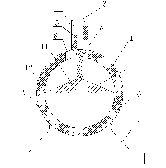
[0011] Such as figure 1 As shown, a pump of the present invention includes a cylindrical pump body 1, a machine base 2 and an end cover 3, the pump body 1 is connected to the joint 4 above it, the end cover 3 is installed above the joint 4, and a hollow is provided in the joint 4 Cavity 5, the cavity 5 of the joint 4 is equipped with a baffle 6, the baffle 6 moves along the cavity 5, the lower end of the baffle 6 is in contact with the rotor 7, the rotor 7 is placed in the pump body 1, and the upper end of the pump body 1 is in the middle There is a hole on the side, and the baffle divides the hole into a liquid inlet 8, and a liquid outlet 9 and a spare liquid outlet 10 are symmetrically opened on both sides of the lower end of the pump body 1. The cross-sectional shape of the rotor 7 is an isosceles triangle, isosceles The base 11 of the triangle is on the same line as the axis of the pump body 1 , and the left and right points 12 of the isosceles triangle are tangent to the...


PUM


Abstract

The invention discloses a pump which comprises a pump body, a base and an end cover, wherein the pump body is connected with a joint above the pump body; the end cover is installed above the joint; a cavity is arranged inside the joint; a baffle plate is installed in the cavity of the joint; the baffle plate moves along the cavity; the lower end of the baffle plate contacts a rotor; the rotor is arranged in the pump body; a hole is formed on one side in the middle of the upper end of the pump body; the hole is isolated into a liquid inlet through the baffle plate; and a liquid outlet and an alternative liquid outlet are formed in symmetry on two sides of the lower end of the pump body. Compared with an ordinary pump, the pump has the advantages that the rotor of the pump can be tangent to the inner chamber of the pump body and is in tight contact with the lower end of the baffle plate, the pump can do work at a speed larger than zero, and the pump is larger in dust flying, smaller in pulse and smaller in part abrasion than the ordinary pump.

Description

technical field [0001] The invention relates to a conveying device for increasing fluid pressure, in particular to a pump. Background technique [0002] At present, the pumps on the market are divided into water pumps, oil pumps and air pumps. The flow rate of the water pump is large, but the outlet pressure is small, the dust of the single machine is small, and the cavitation allowance is large. In order to obtain the work of high dust and large flow, people have to adopt multi-pole The result is that the overall efficiency of the pump unit will be reduced and the cost of use will be increased; while the oil pump has the disadvantages of high pressure, small flow, and short service life due to pulsation. Therefore, it is necessary to provide a new technical solution to solve the above problems. Contents of the invention [0003] The object of the present invention is to provide a pump with less pulsation and less wear on parts. [0004] The technical scheme adopted in t...

Claims


Application Information

Patent Timeline
Patent Type & Authority Applications(China)
IPC IPC(8): F04C2/356
Inventor 秦永
Owner 秦永
Why Eureka
Try Eureka