Self-locking anti-loosening hoop

A self-locking and clamp technology, applied in hose connection devices, mechanical equipment, pipes/pipe joints/fittings, etc., can solve the problem that threaded connections have no self-locking structure, unsatisfactory anti-loosening effect, and poor tightening effect, etc. problem, to achieve good anti-loosening effect, increase market share and save business expenses

Inactive Publication Date: 2013-04-03
SANY HEAVY IND CO LTD (CN)
View PDF6 Cites 3 Cited by
  • Summary
  • Abstract
  • Description
  • Claims
  • Application Information

AI Technical Summary

Problems solved by technology

[0006] 1) After the T-shaped clamp is tightened, it is pre-tightened by a spring to form a flexible connection. The clamp body can increase or decrease at will with the diameter of the

Method used


Image

  • Self-locking anti-loosening hoop
  • Self-locking anti-loosening hoop
  • Self-locking anti-loosening hoop

Examples


Embodiment Construction

[0035] In order to understand the above-mentioned purpose, features and advantages of the present invention more clearly, the present invention will be further described in detail below in conjunction with the accompanying drawings and specific embodiments. It should be noted that, in the case of no conflict, the embodiments of the present application and the features in the embodiments can be combined with each other.

[0036] In the following description, many specific details are set forth in order to fully understand the present invention. However, the present invention can also be implemented in other ways than described here. Therefore, the protection scope of the present invention is not limited by the specific implementation disclosed below. Example limitations.

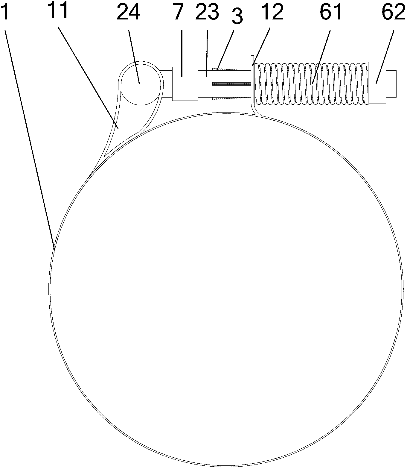
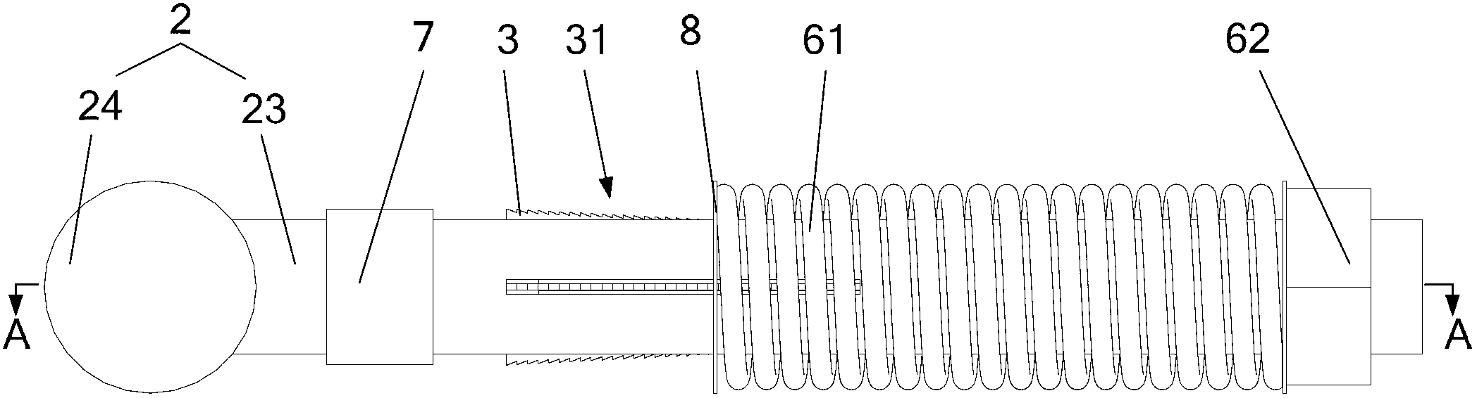
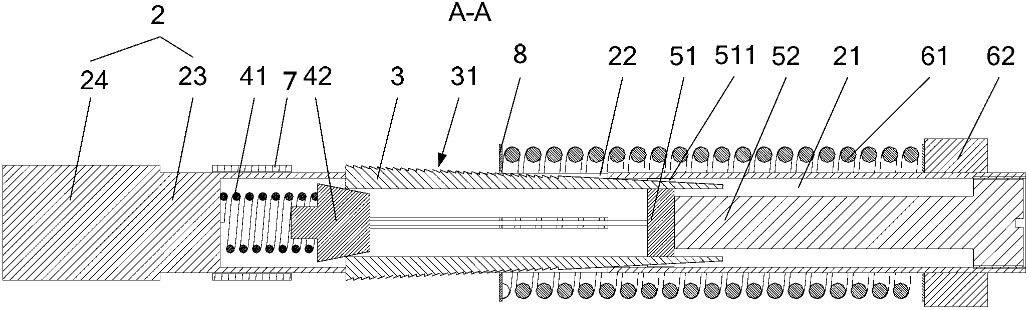
[0037] The self-locking anti-loosening clamp provided by the present invention, such as Figure 1 to Figure 3As shown, it includes a clamp body 1, a connecting body 2, a first elastic device, a second elasti...


PUM


Abstract

The invention provides a self-locking anti-loosening hoop, which comprises a hoop body, a connector, a first elastic device, a second elastic device, an anti-loosening device and a support device, wherein one end of the connector is sleeved with the first end of the hoop body, the other end of the connector passes through the second end of the hoop body, and is matched with the first elastic device; a blind hole is formed in the connector; the hole wall of the blind hole is provided with a first strip-shaped through groove; the second elastic device is arranged in the blind hole; the anti-loosening device is accommodated in the first through groove; one end of the anti-loosening device is a free end, and is supported through the second elastic device in the blind hole, and the other end of the anti-loosening device extends into the blind hole and is supported at a set position in the blind hole through the support device; and the second end of the hoop body can be matched with the anti-loosening device. Due to the adoption of the self-locking anti-loosening hoop, the diameter of the hoop body can be used for automatically compensating the reduction in the thickness of an orifice wall, the hoop body is always jointed tightly with the outer wall surface of an orifice, single-direction locking is realized, and shrink torque is ensured effectively; and the self-locking anti-loosening hoop can be applied to occasions with high mechanical vibration to prevent orifice loosening caused by vibration.

Description

technical field [0001] The invention relates to the field of engineering machinery, in particular to a self-locking anti-loosening clamp. Background technique [0002] When the rubber tube is heated and causes the rubber at the nozzle to flow and the wall thickness of the nozzle becomes thinner or the nozzle shrinks due to cold, a gap is formed between the inner surface of the clamp body and the outer wall of the rubber nozzle, and the clamp body loses its fastening to the nozzle, making the rubber The tube comes loose easily. [0003] The existing T-shaped anti-loosening clamps generally adopt self-locking nuts and spring pre-tightening measures. Although they can achieve a certain effect of diameter compensation and anti-loosening, this process is flexible and often reversible: When the nut is tightened and the spring is preloaded, the diameter of the clamp body can increase or decrease arbitrarily with the change of the nozzle size, and the locking effect is not very sat...

Claims


Application Information

Patent Timeline
IPC IPC(8): F16L33/06
Inventor 宋宇张先腾刘艳绒
Owner SANY HEAVY IND CO LTD (CN)
Why Eureka
Try Eureka