Method for designing antenna by improving side lobe characteristics of array wave beam directivity diagram

A beam pattern and array antenna technology, applied in the field of array antennas, can solve problems such as the inability to guarantee the side lobe peak value, the unsatisfactory performance of the ZFC method, and the inability to provide side lobe characteristics.

Inactive Publication Date: 2013-04-03
HARBIN ENG UNIV
View PDF1 Cites 19 Cited by
  • Summary
  • Abstract
  • Description
  • Claims
  • Application Information

AI Technical Summary

Problems solved by technology

[0034] The performance of the zero-point constrained ZFC method is not ideal. The reason is that the ZFC fixed zero-point constraint cannot effectively improve the sidelobe characteristics. Ensure that the corresponding side lobe peaks can meet the requirements

Method used


Image

  • Method for designing antenna by improving side lobe characteristics of array wave beam directivity diagram
  • Method for designing antenna by improving side lobe characteristics of array wave beam directivity diagram
  • Method for designing antenna by improving side lobe characteristics of array wave beam directivity diagram

Examples


Embodiment Construction

[0068] In the specification and claims, a circular array antenna with 16 uniformly distributed directional array elements is used as an embodiment to illustrate the design method proposed by the present invention in conjunction with the accompanying drawings. The scope of application of this design method is not limited to circular array antennas, but also applies to uniform linear array antennas. Certain words and symbols are used in the description to express specific calculation processes and mathematical functions, which can be understood by those skilled in the art.

[0069] In this method, the specific process of array design by improving the side lobes of the circular array antenna uniformly distributed by 16 directional array elements is as follows:

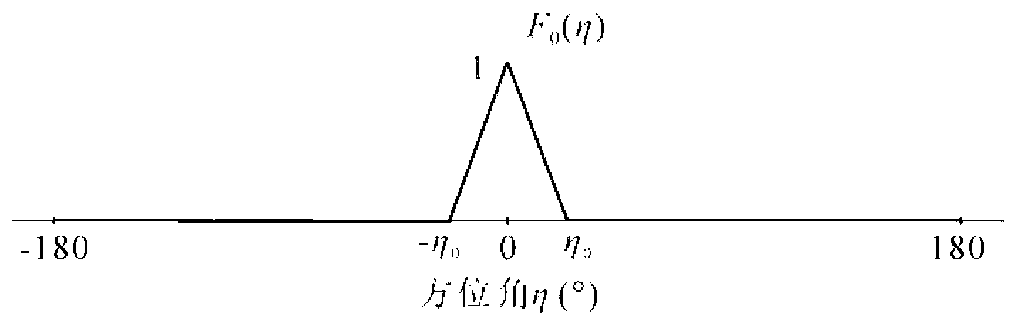
[0070] The first step is to set the desired response pattern A of the array antenna beam.

[0071] Let the expected response pattern A be For such as Figure 5 The uniform circular array with 16 array elements shown, ...


PUM


Abstract

The method relates to a method for designing an antenna by improving the side lobe characteristics of an array wave beam directivity diagram, belonging to the technical field of array antennae. The method comprises the following steps of: setting an expected response directivity diagram A; under the unrestraint condition, determining a array wave directivity diagram B according to a minimum mean square error criterion; selecting a side lobe S to be optimized to determine an interval Omega; under the condition of taking a principle that the directivity diagram amplitude at a k equal division point is zero in the Omega as a constrict condition, calculating an optimal weighting vector Wopt(k) of an array, approaching to the directivity diagram A, according to the minimum mean square error criterion under the corresponding constraint condition to obtain a directivity diagram Ck, and searching the peak value p1(k) and a peak value p2(k) of side lobes at the left side and the right side of the k equal division point in the Ck; and marking Mr (k)=max{pr2(k), pr1 (k)}, searching a maximum value Mr (krm) in all Mr(k), determining the corresponding Wopt (krm) and a wave beam directivity diagram D, and carrying out array antenna design according to the Wopt (krm) and D. The method disclosed by the invention is used for designing the array antenna by improving the characteristics of the side lobes at the single side or both sides without carrying out hardware improvement on the original array and has the advantages of good flexibility, low cost and good effect.

Description

technical field [0001] The method of the invention relates to the technical field of array antennas. The invention provides a method for designing an antenna by improving the side lobe characteristics of an array beam pattern. Background technique [0002] Array antennas are widely used in many fields such as radar, wireless communication, direction finding, and radio astronomy. The array antenna can use the spatial characteristics of the signal to filter the signal in the space-time field. [0003] When designing an array antenna, there are two aspects that determine the performance of the array antenna’s spatial filtering. One is that the geometric structure of the array antenna constitutes the basic limit of the array antenna’s performance. weighted. Under the condition of a given geometric structure of the array antenna, the selection of these weights determines the characteristics of the array antenna's beam pattern, that is, determines the characteristics of the arr...

Claims


Application Information

Patent Timeline
Patent Type & Authority Applications(China)
IPC IPC(8): G06F17/50H01Q21/24
Inventor 张曙李亮栾晓明
Owner HARBIN ENG UNIV
Why Eureka
Try Eureka