A wind power generation system
A technology of wind power generation system and power system, which is applied in the direction of wind power generation, wind power engine, wind power motor combination, etc., and can solve problems such as blade over-rotation and speed increase
- Summary
- Abstract
- Description
- Claims
- Application Information
AI Technical Summary
Problems solved by technology
Method used
Image

Examples
Embodiment 1
[0095] In this embodiment, an example of the wind power generation system 1 in which the power converter is cooled by cooling water will be described.
[0096] The wind power generation system 1 of this embodiment converts wind energy into electric power with a generator including blades and permanent magnets, and converts the electric power into a commercial frequency with a power converter to transmit electric power to an electric power system.
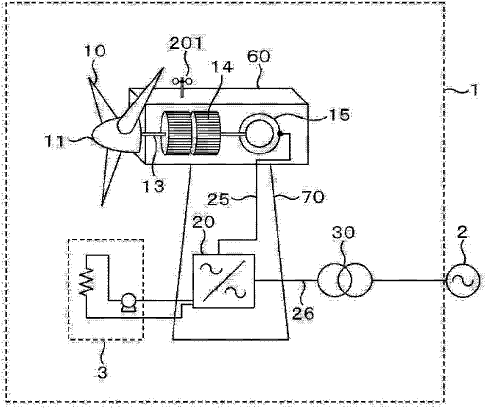
[0097] figure 1 A configuration example of the wind power generation system 1 of this embodiment is shown.
[0098] The wind power generation system 1 is provided with: a blade 10 that converts wind energy into rotational energy, a hub 11 that supports the blade and transmits the rotational force of the blade to a shaft, a shaft 13 that transmits the rotational force to a gear 14, and is mechanically connected to the gear. A generator 15 that converts rotational energy into electrical energy, a power converter 20 that converts the ...
Embodiment 2
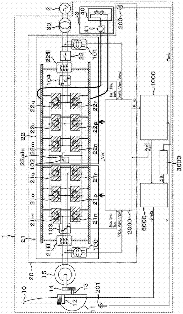
[0157] In this embodiment, an example of the wind power generation system 1 in which the cooling capacity is detected from the internal temperature of the power converter will be described.
[0158] Figure 11 It is an example of a configuration diagram showing the wind power generation system 1 of the first embodiment.
[0159] for with figure 1 The wind power generation system 1 has been explained figure 1 The description of the parts with the same functions assigned to the same symbols will be omitted.
[0160] The difference between the present embodiment and the wind power generation system described in the first embodiment is that the temperature sensor 200 is installed in the frame housing the converter 21 and the inverter 22 of the power converter 20 .
[0161] In Embodiment 1, the temperature of the cooling water is detected directly or indirectly through ambient temperature detection to detect the decrease in the cooling capacity of the cooling system 3 that cools...
Embodiment 3
[0175] In this embodiment, an example of the wind power generation system 1 in which the cooling capacity is detected from the internal temperature of the power converter will be described.
[0176] Figure 13 It is an example of a configuration diagram showing the wind power generation system 1 of the first embodiment.
[0177] for with figure 1 The wind power generation system 1 has been explained figure 1 The components shown with the same symbols have the same functions, and their descriptions are omitted.
[0178] The difference between this embodiment and the wind power generation system described in Embodiment 2 is that the temperature sensor 200 is provided on the cooling fin of the semiconductor element of the power converter 20 .
[0179] In a water-cooled power converter, when the thermal time constant of the cooling fin is short and the cooling capacity of the cooling system 3 decreases, the junction temperature of the semiconductor element exceeds the allowable...
PUM
 Abstract
Description
Claims
Application Information
 - R&D Engineer
- R&D Manager
- IP Professional
- Industry Leading Data Capabilities
- Powerful AI technology
- Patent DNA Extraction
Browse by: Latest US Patents, China's latest patents, Technical Efficacy Thesaurus, Application Domain, Technology Topic.
© 2024 PatSnap. All rights reserved.Legal|Privacy policy|Modern Slavery Act Transparency Statement|Sitemap