Configuration of the communication links of field devices in a power automation installation

A technology of field equipment and facilities, applied in the field of data processing devices

Active Publication Date: 2013-04-03
SIEMENS AG
View PDF3 Cites 2 Cited by
  • Summary
  • Abstract
  • Description
  • Claims
  • Application Information

AI Technical Summary

Problems solved by technology

Manual settings come with a high risk of errors, and finding these errors after the fact is very cumbersome

Method used


Image

  • Configuration of the communication links of field devices in a power automation installation
  • Configuration of the communication links of field devices in a power automation installation
  • Configuration of the communication links of field devices in a power automation installation

Examples


Embodiment Construction

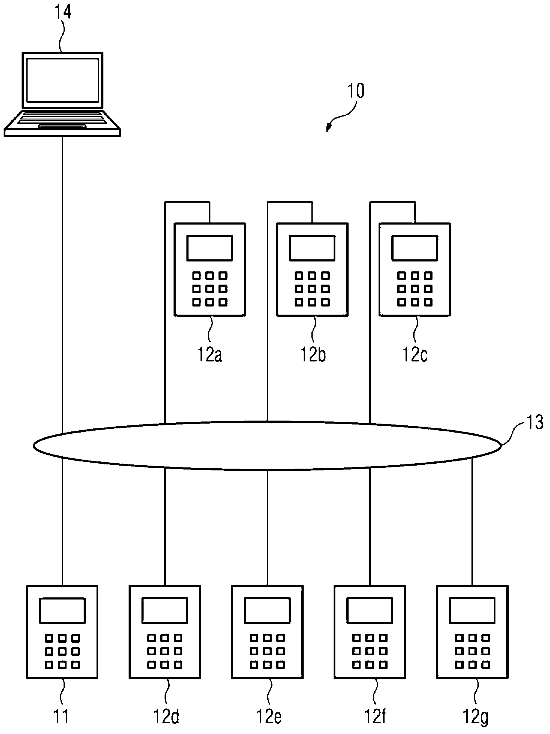
[0031] figure 1 The energy automation facility 10 is shown for the sake of clarity not in figure 1 Control and monitor the power supply network shown in . The energy automation system 10 has a first field device 11 , wherein the first field device is, for example, an electrical protection device or a control technology device. Such and other field devices for the automation of energy supply networks are often also referred to as so-called “IEDs” (IED=“Intelligent Electronic Device”) in technical terminology. In the following, the term "field device" is used not only for protection devices, control technology devices, measuring devices (RTUs), but also for other automation devices for energy automation systems which are usually included in the concept IED.

[0032] The energy automation system 10 also contains further field devices 12a to 12g. In order to exchange data telegrams with one another, the field devices 11 and 12 a to 12 g have communication devices which have int...


PUM


Abstract

In order to specify a method for configuration of field devices (11, 12a-12g), in which a user can carry out configuration processes with a high level of confidence against incorrect settings, even without extensive knowledge of a set of rules governing the communication, it is proposed that a graphics editor (30) has a first display area (31), which comprises a graphics display (33) of functions of a first field device (11), and has a second display area (32) which comprises a graphics display (36a, 36b) of at least one further field device (12a-12g) which is connected to the first field device (11), and an indication (37a, 37b) of possible output signals, a selection by the user of an output signal from the at least one further field device (for example 12a) and of a function of the first field device (11) is detected, and parameter sets are produced for the first field device (11); and for the at least one further field device (for example 12a), which parameter sets comprise instructions for configuration of the communication link of the first field device (11) and of the at least one further field device (for example 12a) which, when a selected output signal is present for the at least one further field device (for example 12a), indicate that a data message has been sent to the first field device (11) and that the selected function of the first field device (11) has been initiated. The invention also relates to a correspondingly designed power automation installation (10).

Description

technical field [0001] The invention relates to a method for configuring field devices of an energy automation system and to a data processing device by means of which such a configuration can be carried out. Background technique [0002] Energy automation installations are used for the automation of the power supply network and usually contain so-called field devices, which are arranged at main components of the power supply network near. Such main components may be, for example, cables and wires, transformers, generators, electric motors or converters. Usually, electrical field devices record measured values ​​which describe the operating state of the individual main components of the power supply network. These measured values ​​can be stored or forwarded to control and monitoring components superordinate to the individual field devices. In addition, the field devices, which are designed as so-called "protective devices", can be designed to check the recorded measured...

Claims


Application Information

Patent Timeline
IPC IPC(8): G05B19/042G05B19/418
CPCG05B19/41845G05B19/0426G05B2219/31339Y02P90/02H02J4/00
Inventor T.杰赫曼G.赖肯巴赫N.舒斯特
Owner SIEMENS AG
Why Eureka
Try Eureka