
Turntable

A technology of turntable and support surface, which is applied in the direction of recording information storage, instruments, etc., and can solve problems such as difficult focus control

Active Publication Date: 2013-04-03
PANASONIC CORP
View PDF5 Cites 0 Cited by
  • Summary
  • Abstract
  • Description
  • Claims
  • Application Information

AI Technical Summary

Problems solved by technology

In addition, it is known that in general, when the rotation speed of the turntable fluctuates, slippage between the corresponding disk support surface and the disk member is likely to occur, and it is difficult to perform proper focus control when such slippage occurs.

Method used


Image

  • Turntable
  • Turntable
  • Turntable

Examples


Embodiment Construction

[0057] Hereinafter, embodiments of the present invention will be described in detail with reference to the drawings.

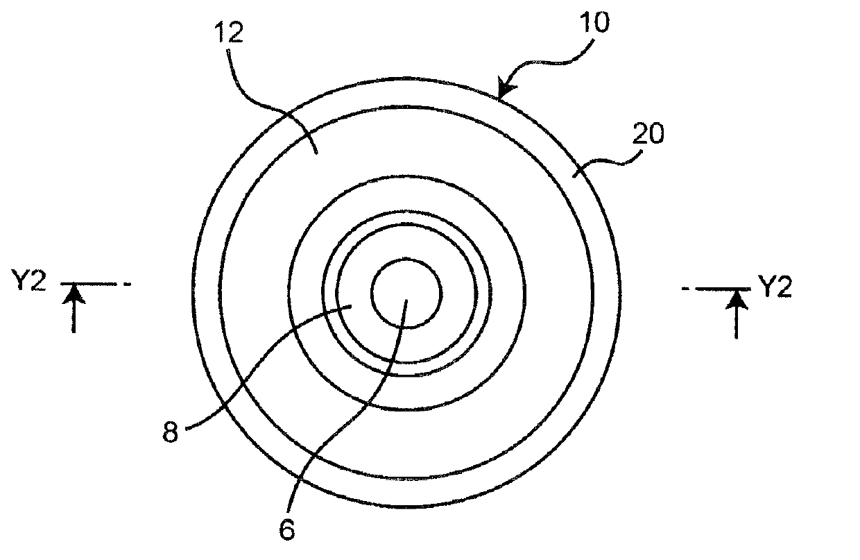
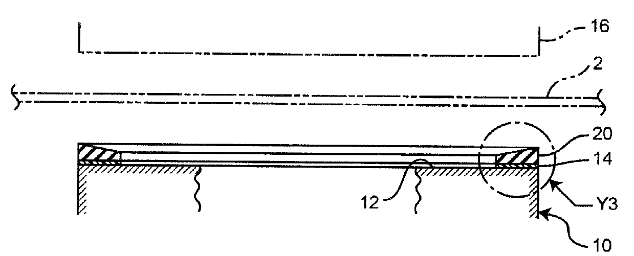
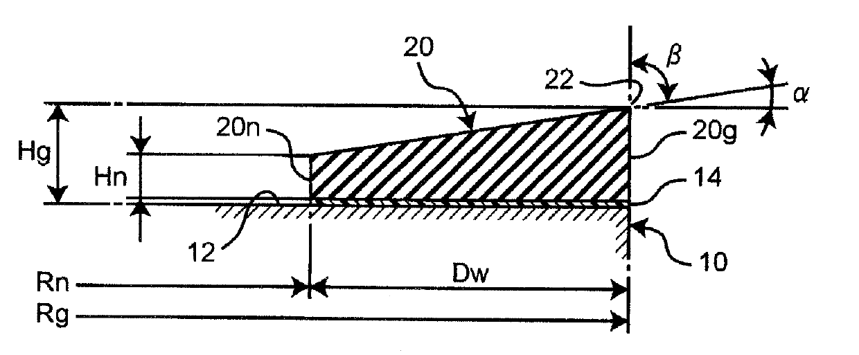
[0058] figure 1 It is a plan view schematically showing a schematic configuration of a turntable according to an embodiment (first embodiment) of the present invention, figure 2 is along figure 1 A schematic longitudinal sectional view of the turntable on line Y2-Y2, additionally image 3 is enlarged figure 2 An enlarged longitudinal sectional view of the main part of Y3.

[0059] As shown in these figures, the turntable 10 according to the present embodiment includes a disk supporting surface 12 on which a disk member 2 such as an optical disk is placed, and an output shaft 6 of a spindle motor (not shown) is integrally assembled at the center thereof. The clamp member 16 is arranged to face the disk support surface 12 of the turntable 10 . As will be described in detail later, on the disk support surface 12, an elastic layer 20 of a predetermined widt...


PUM

PropertyMeasurementUnit
diameteraaaaaaaaaa

Abstract

The objectives of the present invention are to allow the effect of preventing relative slippage between a disk-supporting surface and a disk member to be retained even when dust has adhered to the surface of an elastic layer provided on the disk-supporting surface of the turntable, and to suppress face runout of the disk member while spinning when the elastic layer is provided on the disk-supporting surface. The turntable supports the disk member mounted on the disk-supporting surface in a rotatable manner with the disk member sandwiched between the turntable and a clamping member that is positioned so as to face the turntable. The turntable is characterized by being equipped with an elastic layer of a predetermined width, which is provided on the disk-supporting surface so as to protrude from the disk-supporting surface, and the elastic layer has at the peripheral part an edge section serving as a high-pressure contact part where the contact pressure from the clamping member is higher than at other parts.

Description

technical field [0001] The present invention relates to a turntable for rotatably supporting a disk component such as an optical disk. Background technique [0002] As is well known, in a so-called disk device that reproduces information signals recorded on a disk-shaped recording medium such as an optical disk and / or records information signals on a disk-shaped recording medium, a rotatable A turntable for supporting the disc-shaped recording medium. [0003] In the corresponding disk device, after the disk-shaped recording medium is placed on the disk-supporting surface of the turntable, the disk-shaped recording medium is clamped between the disk-supporting surface and clamp members arranged oppositely. For example, a motor (so-called spindle motor) having an integrally assembled output shaft is driven for the turntable, thereby rotationally driving the turntable that supports the disk-shaped recording medium on the disk support surface. In this case, the disk clamping ...

Claims


Application Information

Patent Timeline
Patent Type & Authority Applications(China)
IPC IPC(8): G11B17/028
CPCG11B17/0284G11B17/0282
Inventor 仲昭行前田真一有吉祐二丸山益生高桥宏
Owner PANASONIC CORP
Learn More