Light detector to control a hybrid lamp

A technology of light sensor and power control module, which is applied in the field of lamp components, and can solve the problem of insufficient precision of the solution

Inactive Publication Date: 2013-04-10
GENERAL ELECTRIC CO
View PDF0 Cites 0 Cited by
  • Summary
  • Abstract
  • Description
  • Claims
  • Application Information

AI Technical Summary

Problems solved by technology

Also, this solution is not sufficiently precise as various conditions may suggest different time periods

Method used


Image

  • Light detector to control a hybrid lamp
  • Light detector to control a hybrid lamp

Examples


Embodiment Construction

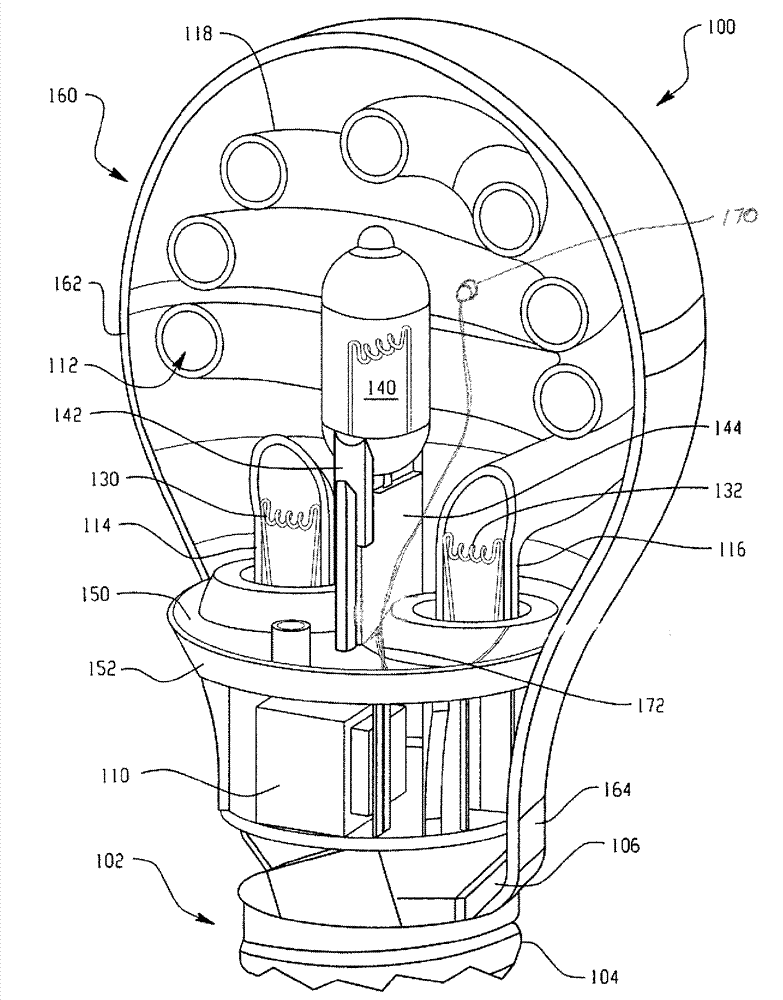
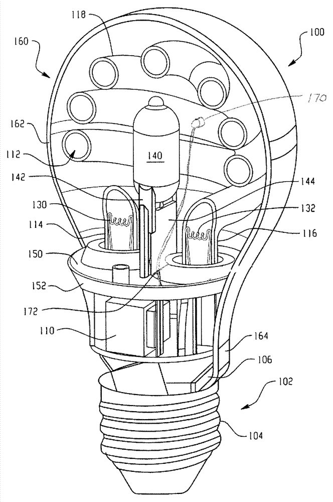
[0033] 1 and 2 illustrate a lamp assembly 100, and more particularly, a discharge lamp source, or preferably a fluorescent lamp source, such as a compact fluorescent lamp (CFL) assembly (collectively referred to herein as an energy-saving lamp or light source) and an advantageous A combination of secondary light sources such as incandescent lamp assemblies that provide instantaneous light. Lamp head 102 includes mechanical and electrical arrangements for receipt in an associated lamp socket (not shown) to mechanically support lamp assembly 100 and to provide power to operate the lamp assembly. More specifically, and need not be limiting, a conventional Edison lamp cap 102 is shown, which includes a conductive threaded metal housing 104 for threadingly received in an associated lamp socket, and typically includes an electrical eyelet or second Contacts (not shown), which are separated from the threaded housing 104 by insulating material at the lower end of the lamp assembly. T...


PUM


Abstract

The present invention relates to a light detector to control a hybrid lamp. A lamp assembly (100) provides both instant light through use of an incandescent / halogen lamp source (140) and an energy saving type light provided by a compact fluorescent lamp source (112). Both light sources are enclosed within a common envelope or outer bulb (160). The sensor member (170) monitors light output from a central region of the CFL at a region spaced from the first and second ends in order to obtain an accurate representation of full light output from the CFL before shutting off or terminating power to the incandescent lamp source.

Description

technical field [0001] The present disclosure relates to light assemblies, such as light assemblies that provide energy savings and also provide for instant light. Background technique [0002] One proposed solution to shorten the time to full light while still obtaining the benefits of a CFL is to combine two lamps in one unit. More specifically, compact fluorescent lamps (CFLs) and conventional incandescent lamps are combined. While it is recommended to turn on both lamps at the same time to result in instantaneous light from the incandescent, and then subsequently terminate or switch off the incandescent to obtain the benefit of an energy efficient CFL, these known configurations do not provide for determining when to turn off the incandescent (i.e., An efficient and efficient way to use exclusively compact fluorescent lamps once the CFLs get hot. [0003] There is no light emission from the CFL lamp until warm-up is complete. Once arcing begins, compact fluorescent la...

Claims


Application Information

Patent Timeline
Patent Type & Authority Applications(China)
IPC IPC(8): F21S2/00F21V23/04
CPCH05B35/00Y02B20/00
Inventor P.卢茨P.维L.班库蒂B.托罗克
Owner GENERAL ELECTRIC CO
Why Eureka
Try Eureka