Brushless direct-current (DC) motor

A technology of DC motors and motor shafts, applied in the direction of electric components, electrical components, electromechanical devices, etc., can solve problems that affect the wide application of brushless DC motors, restrict the development of brushless DC motors, and reduce the reliability of brushless DC motors. , to achieve significant economic and social benefits, reduce operational failures, and increase reliability

Inactive Publication Date: 2013-04-10
河北首力科技有限公司
View PDF5 Cites 5 Cited by
  • Summary
  • Abstract
  • Description
  • Claims
  • Application Information

AI Technical Summary

Problems solved by technology

In the structure of the brushless DC motor with Hall element installed, the Hall element is close to the rotor magnetic steel, and because the rotor and the stator are very close, if the temperature of the stator exceeds the rated value, the Hall element will be damaged first. The failure of brushless DC motors caused by component damage is a common fault of brushless DC motors, which reduces the reliability of brushless DC motor operation and affects the wide application of brushless DC motors
This situation has not been effectively resolved, and it has become a hidden danger restricting the development of brushless DC motors, which urgently needs to be improved.

Method used


Image

  • Brushless direct-current (DC) motor

Examples


Embodiment Construction

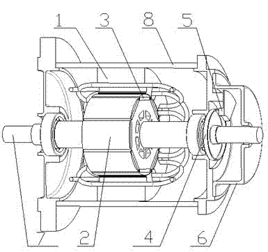
[0013] The brushless DC motor of the present invention includes a casing 8 , a motor shaft 7 , a stator 1 , a rotor 2 , a magnetic steel 3 , a magnetic ring 4 and a Hall element 5 .

[0014] As shown in the figure, the rotor 2 is installed on the motor shaft 7, the magnet steel 3 is installed on the rotor 2, and the stator 1 is outside the rotor 2.

[0015] The figure shows that a magnetic ring 4 is fixed on the motor shaft 7 outside the casing 8, and a Hall element 5 is installed on the outer wall of the casing 8. The distance between the Hall element 5 and the magnetic ring 4 is smaller than the sensing range of the Hall element 5. The Hall element 5 is connected with the controller. A protective cover 6 is installed outside the Hall element 5 , and the edge of the protective cover 6 is connected with the outer wall of the motor casing 8 .

[0016] After the stator 1 is energized in the present invention, the rotor 2 rotates, the rotor 2 drives the motor shaft 7 to rotate, ...


PUM


Abstract

The invention belongs to the technical field of brushless direct current motors, discloses a brushless direct-current (DC) motor, and aims at preventing a Hall element from being damaged due to the fact that the temperature of a stator rises. The brushless DC motor comprises a shell, a motor shaft, the stator, a rotor and a magnetic steel piece, wherein a magnetic ring is fixed on the portion, outside the shell, of the motor shaft, the Hall element is mounted on the outer wall of the shell, the distance between the Hall element and the magnetic ring is shorter than an induction range of the Hall element, and the Hall element is connected with a controller. The Hall element is arranged outside the DC motor, the Hall element cannot be affected by the rise of the temperature inside the DC motor and cannot be damaged due to the rise of the temperature of the Hall element. According to the brushless DC motor, the structural mode of a traditional DC motor is broken through, a convention is broken, the Hall element is innovatively arranged outside the shell of the motor, an unexpected effect is obtained, a hard problem which is not solved in a long term is solved, operation troubles of the brushless DC motor can be reduced greatly, and reliability of the brushless DC motor is greatly improved.

Description

technical field [0001] The invention relates to a brushless DC motor with an external Hall element, belonging to the technical field of brushless DC motors. Background technique [0002] With the advancement of motor technology, the performance of brushless DC motors has been continuously improved, showing the advantages of excellent performance, various control methods, material saving, energy saving, and long service life, and has been more and more widely used. However, the weakest link of the existing brushless DC motor is that the Hall element of the brushless DC motor is easily damaged. The Hall element is one of the core components of the brushless DC motor. During the working process of the brushless DC motor, the Hall element controls the brushless DC motor by detecting the position of the magnet. When the Hall element is damaged, the brushless DC motor will stop working immediately and must be repaired. Therefore, the quality of the Hall element is directly relat...

Claims


Application Information

Patent Timeline
Patent Type & Authority Applications(China)
IPC IPC(8): H02K29/08H02K11/00H02K11/215
Inventor 李斌张林海
Owner 河北首力科技有限公司
Why Eureka
Try Eureka