Discharge valve assembly for two-stroke engine, provided with cooling, non-contacting seal and self-cleaning

A technology of valve components and exhaust valves, applied in engine components, engine control, combustion engines, etc., can solve environmental pollution and other problems, and achieve the effect of eliminating thermal problems

Inactive Publication Date: 2013-04-10
E2F DI ESPOSTI FEDERICI ETTORE
View PDF10 Cites 2 Cited by
  • Summary
  • Abstract
  • Description
  • Claims
  • Application Information

AI Technical Summary

Problems solved by technology

The above results will lead to serious environmental pollution

Method used


Image

  • Discharge valve assembly for two-stroke engine, provided with cooling, non-contacting seal and self-cleaning
  • Discharge valve assembly for two-stroke engine, provided with cooling, non-contacting seal and self-cleaning
  • Discharge valve assembly for two-stroke engine, provided with cooling, non-contacting seal and self-cleaning

Examples


Embodiment Construction

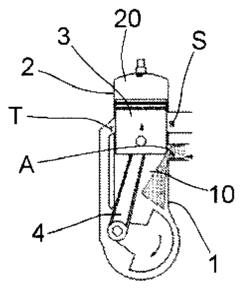
[0046] With reference to the aforementioned figures, the exhaust valve assembly of the present invention is described, generally indicated by the reference numeral (100).

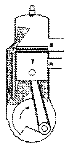
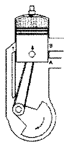
[0047] figure 2 A two-stroke internal combustion engine (200) is shown coupled to an exhaust box (300). Parts of an internal combustion engine (200) are used for Figure 1A~1F The same reference numerals are used in the description of , and thus their detailed descriptions are omitted.

[0048]The exhaust valve assembly (100) is installed downstream of the exhaust port (S) of the cylinder (2) of the engine. The valve assembly (100) can be integrally formed with the casing of the engine (200), or as an independent component, arranged between the casing of the engine (200) and the exhaust box (300).

[0049] refer to image 3 with Figure 4 , the valve assembly (100) includes a housing (5) and a valve (7) rotatably mounted on the housing (5).

[0050] refer to Figure 5 , the valve (7) is substantially...


PUM


Abstract

A discharge valve assembly (100) for two-stroke internal combustion engine (200) is disclosed, comprising a cylindrical shutter (7) revolvingly mounted into a housing (5). A canal (8) is left between the external surface of the shutter (7) and the internal surface of the housing (5) to avoid contact between surfaces and ensure valve seal.

Description

technical field [0001] The patent application for this industrial invention relates to an exhaust valve assembly for a two-stroke engine. Background technique [0002] As we all know, a two-stroke engine is an internal combustion engine used in the work phase, also defined as expansion, in which chemical energy is converted into thermal energy and then into kinetic energy. A two-stroke engine differs from most popular four-stroke engines primarily in the alternating phases of work according to the rotation of the drive shaft. In fact, a four-stroke engine has one power phase for every two revolutions of the drive shaft, while a two-stroke engine has one power phase for every complete revolution of the drive shaft. [0003] Figure 1A~1F Schematic illustration of a two-stroke internal combustion engine in different working stages. The internal combustion engine comprises a cylinder head (1), a cylinder (2) mounted on the cylinder head, a piston (3) slidably mounted in the c...

Claims


Application Information

Patent Timeline
IPC IPC(8): F01L7/12F02B33/04F01L7/02
CPCF01L7/023F01L7/12F02B25/04F02B33/04F02D9/04F02D9/16F02D13/028Y02T10/12F01L7/02F01L7/021
Inventor 埃托雷·埃斯波斯蒂费代里奇
Owner E2F DI ESPOSTI FEDERICI ETTORE
Why Eureka
Try Eureka