Leak detector

A leak detection and sensor technology that can solve problems such as affecting optical properties and fiber deformation by detecting the presence of fluids, instruments, measuring devices, etc. at the leak point

Inactive Publication Date: 2013-04-10
DUNLOP OIL & MARINE
View PDF6 Cites 5 Cited by
  • Summary
  • Abstract
  • Description
  • Claims
  • Application Information

AI Technical Summary

Problems solved by technology

In some detectors, the optical fiber is coated with a fluid-sensitive material that bulges upon contact with the fluid, causing deformation of the optical fiber and thereby affecting its optical properties

Method used


Image

  • Leak detector
  • Leak detector
  • Leak detector

Examples


Embodiment Construction

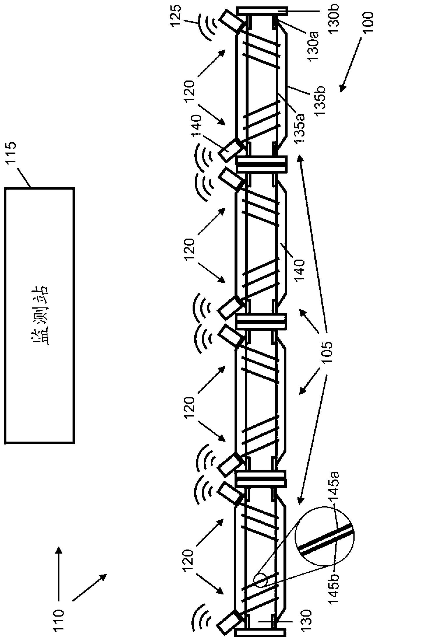
[0022] refer to figure 1 , the underwater hose 100 is formed from connected hose sections 105 and in use is submerged underwater. The leak detection system 110 consists of a monitoring station 115 and a plurality of sensor devices 120 , two mounted to each hose section 105 of the hose 100 . Each sensor device 120 independently communicates with monitoring station 115 via transmitted sonar signals 125 . In other embodiments, the hose 100 is not submerged (eg, it floats on the surface of the water), and the transmitted signal 125 is an electromagnetic signal.

[0023] The hose sections 105 are connected to each other at their ends to form the hose 100 . A hose end fitting 130 is located at each end of the individual hose sections 105 by which the hose sections 105 are connected together. Each end fitting 130 consists of a tubular portion 130a connected to a larger diameter flange 130b. A hole is formed through the flange 130b through which the respective end fittings 130 of ...


PUM


Abstract

A leak-detecting sensor device (120) for a hose section (105) comprises a sensor(145a, b). The sensor (145a, b) comprises an optical fibre arranged to react to the presence of a fluid. The sensor (145a, b) is housed in a protective sleeve that is arranged for expansion and contraction when the hose section (105) expands and contracts, respectively. Tension means connects a first end of the sensor to the protective sleeve and is arranged to tension the sensor within the sleeve.

Description

technical field [0001] The present invention relates to the detection of leaks, in particular to the detection of fluid leaks in hoses. Background technique [0002] Subsea hoses, such as fuel hoses, generally experience wear and tear, as well as aging, and may be subject to other forms of damage. This can lead to rupture of the hose, resulting in leakage of the hose contents or water ingress from the outside of the hose. Typically, underwater hoses include an inner carcass and an outer carcass, both of which may rupture at any point along the hose. Failure of the outer carcass will result in the ingress of water, while failure of the inner carcass will result in leakage of the fluid conveyed by the hose. A detector is typically placed at the end of the hose section and detects a leak when fluid or water from the leak reaches the end of the hose section. It is obvious that it is beneficial to detect any leak as quickly as possible and to detect the location and type of le...

Claims


Application Information

Patent Timeline
IPC IPC(8): G01M3/04
CPCG01M3/047G01M3/04F16L1/11F16L11/12G01M3/26F16L55/00G01M3/38
Inventor A.R.K.赞迪业P.斯塔顿
Owner DUNLOP OIL & MARINE
Why Eureka
Try Eureka