Novel cubic combination hydraulic machine

A combined structure and six-sided roof technology, which is applied in the field of diamond hydraulic presses, can solve problems such as the inability of man and machine to coordinate, and the inability to adapt to the operation requirements of operators and maintenance personnel, and achieve the effect of facilitating maintenance and maintenance

Inactive Publication Date: 2013-04-17
GUILIN GUIYE HEAVY IND
View PDF3 Cites 2 Cited by
  • Summary
  • Abstract
  • Description
  • Claims
  • Application Information

AI Technical Summary

Problems solved by technology

With the large-scale development of the six-sided top diamond hydraulic press, the traditional hinged beam combination structure is no longer suitable for the operation requirements of operators and maintenance personnel, and has become an obstacle that cannot be coordinated between man and machine.

Method used


Image

  • Novel cubic combination hydraulic machine

Examples


Embodiment Construction

[0014] Below in conjunction with accompanying drawing, technical scheme of the present invention will be further described:

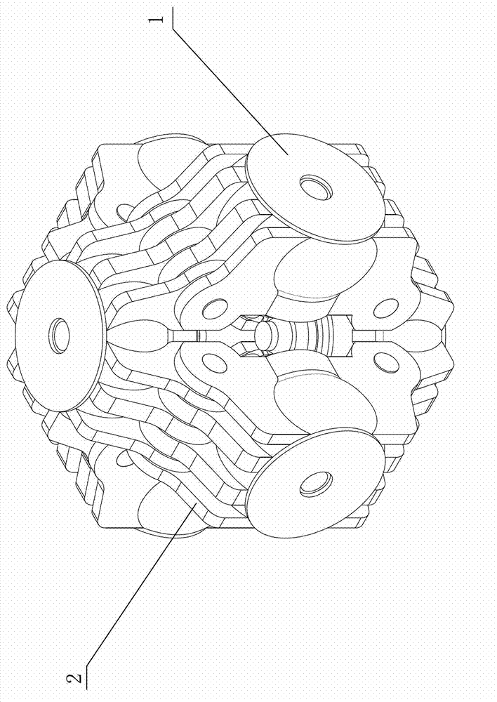
[0015] The upper, lower, front, rear, left and right six hinged beams 1 of the novel six-sided roof combined structure hydraulic press of the present invention are spatially symmetrically arranged.

[0016] The upper and lower hinge beams 1 have respectively downward and upward front, rear, left and right four groups of longitudinal connecting lugs 2, and each group of connecting lugs 2 is three pieces; the front, rear, left and right Hinge beam 1 has two groups of longitudinal connecting lugs 2 up and down without transverse connecting lugs 2, and each group of connecting lugs 2 is four pieces, as figure 1 shown.

[0017] The connecting lugs 2 of the upper and lower hinged beams 1 are hinged with the connecting lugs 2 of the front, rear, left and right hinged beams 1, and the upper and lower hinged beams 1 and the middle hinged beam 1 (front or rear) ...


PUM


Abstract

The invention discloses a novel cubic combination hydraulic machine, which comprises six hinge beam, namely an upper hinge beam, a lower hinge beam, a front hinge beam, a rear hinge beam, a left hinge beam and a right hinge beam arranged in a space symmetry way, wherein the upper hinge beam and the lower hinge beam are provided with four groups of longitudinal connecting lugs in front, rear, left and right directions; the front hinge beam, the rear hinge beam, the left hinge beam and the right hinge beam are provided with two groups of longitudinal connecting lugs in upper and lower directions; the connecting lugs of the upper hinge beam and the lower hinge beam are hinged with those of the front hinge beam, the rear hinge beam, the left hinge beam and the right hinge beam; each group of connecting lugs of the upper hinge beam and the lower hinge beam comprises three connecting lugs; and each group of connecting lugs of the front hinge beam, the rear hinge beam, the left hinge beam and the right hinge beam comprises four connecting lugs. According to the novel cubic combination hydraulic machine, two groups of horizontal connecting lugs are cancelled in the connecting structures of the front hinge beam, the rear hinge beam, the left hinge beam and the right hinge beam, working 'windows' between the longitudinal connecting lugs are expanded, the working distance of material loading or top hammer exchanging is shortened, the man-machine coordination disorder after enlargement of the cubic hydraulic machine is eliminated, and more conveniences are provided for overhaul and maintenance.

Description

(1) Technical field: [0001] The invention relates to a diamond hydraulic press, in particular to a novel six-sided roof combined structure hydraulic press. (2) Background technology: [0002] The six-sided top hydraulic press for superhard materials uses the working principle of the six-sided top to push the six hard alloy anvils synchronously through hydraulic pressure to extrude the synthetic material to generate high pressure, and to generate high temperature through low-voltage and high-power current heating to make the synthetic material The process in which the internal structure of the material undergoes a qualitative change to form a new superhard material. [0003] The structure of the six-sided top diamond hydraulic press is that six working cylinders are arranged in the upper, lower, front, rear, left and right spaces. The working cylinders are axially thrust by the flange and are designed to be supported by the bottom of the hinge beam. thrust. [0004] The hin...

Claims


Application Information

Patent Timeline
IPC IPC(8): B01J3/06
Inventor 郭滇生袁源龚世勇
Owner GUILIN GUIYE HEAVY IND
Why Eureka
Try Eureka